Project Overview
The Modular Autonomous Ground Vehicle, or MAG-V, was developed as a modular rover platform capable of remote driving, sensor-assisted awareness, payload aiming, payload actuation, and future autonomous expansion. The final system was built around a Waveshare rover base, an ESP32-based driver board, a browser-based controller, Bluetooth gamepad support, ultrasonic radar-style sensing, and a servo-driven payload mechanism.
The most difficult part of this project was system integration. The final build required motor control, wireless communication, browser commands, Bluetooth input, OLED feedback, sensor telemetry, servo control, relay actuation, battery monitoring, and safety logic to work together reliably without brownouts, pin conflicts, startup issues, or excessive latency.
My Role
This project was submitted in a group course setting for MENG 4311, but I served as the primary technical lead for the final integrated rover build. I independently completed the core system integration work, including firmware development, wiring architecture, sensor integration, payload control, web interface development, Bluetooth controller integration, subsystem troubleshooting, and final demo preparation.
My documented contributions included setup and procedures, results, bill of materials, electrical diagrams, CAD/model appendices, firmware appendices, and web user interface documentation. The final working build integrated Wi-Fi control, Bluetooth gamepad operation, ultrasonic radar-style sensing, servo payload aiming, relay payload actuation, OLED telemetry, onboard battery monitoring, and emergency-stop behavior.
Final Implemented System
The finished rover combined mechanical design, embedded firmware, wireless control, sensor feedback, payload actuation, and power-management troubleshooting into one working platform.
Wi-Fi Access Point Control
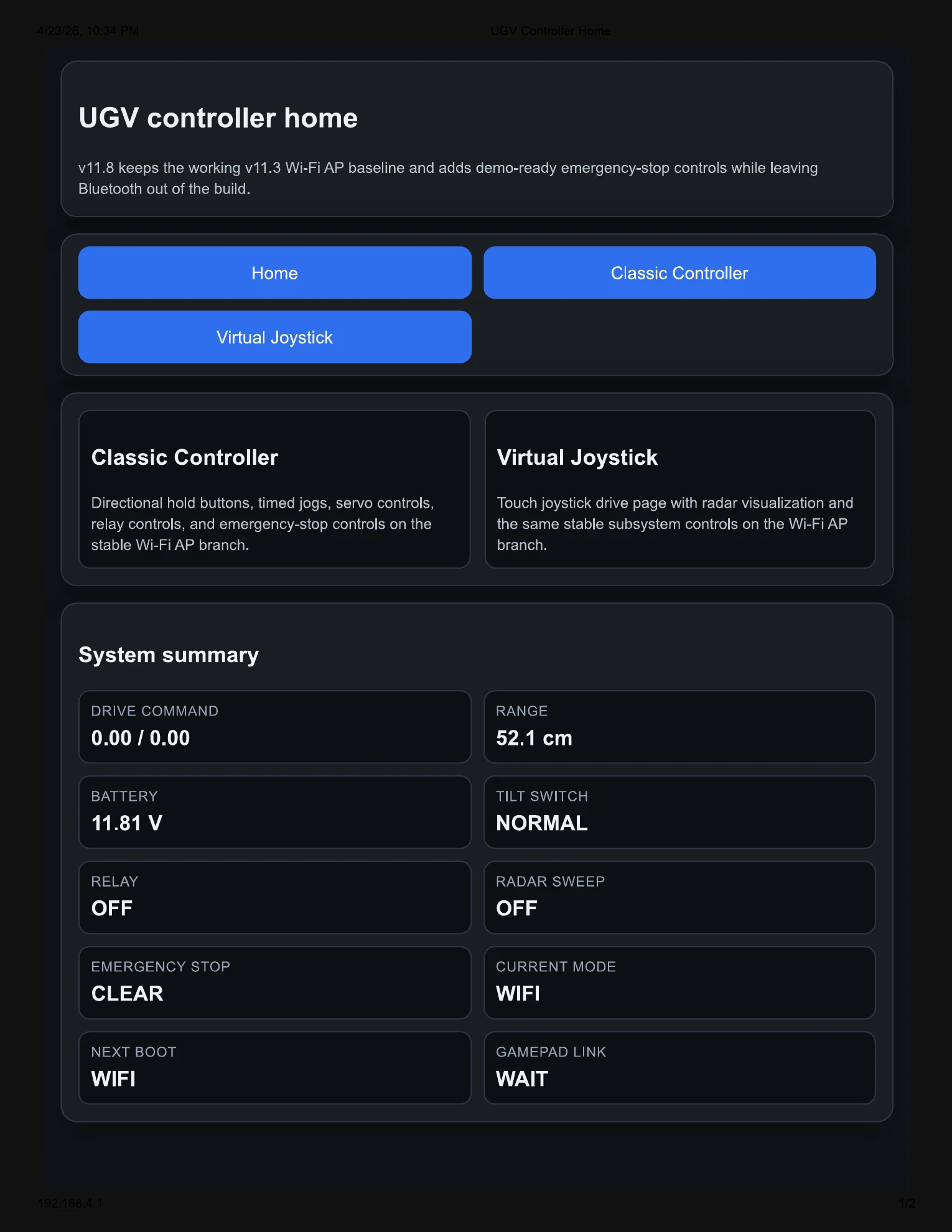
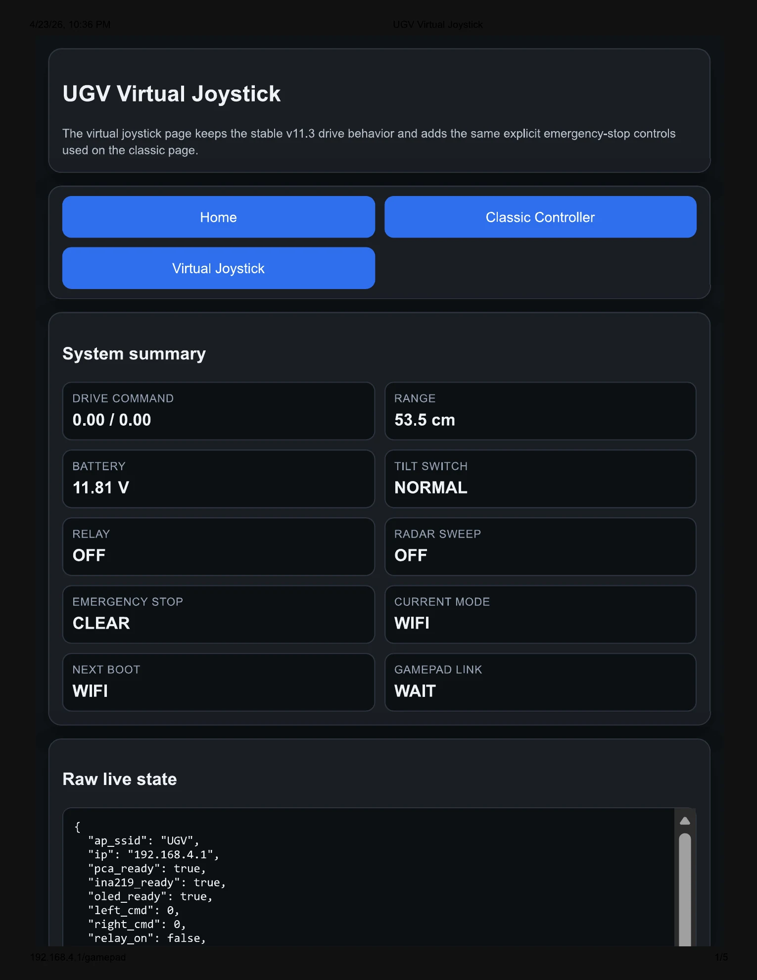
The rover creates its own local Wi-Fi access point and serves a browser-based user interface for telemetry, drive control, payload control, radar visualization, and emergency-stop operation.
Bluetooth Gamepad Mode
The final demo build supports an Xbox One controller. The left stick controls rover motion, the right stick controls payload pan/tilt, and controller buttons handle stop, radar sweep, payload trigger, and next-boot mode selection.
Payload Aiming and Triggering
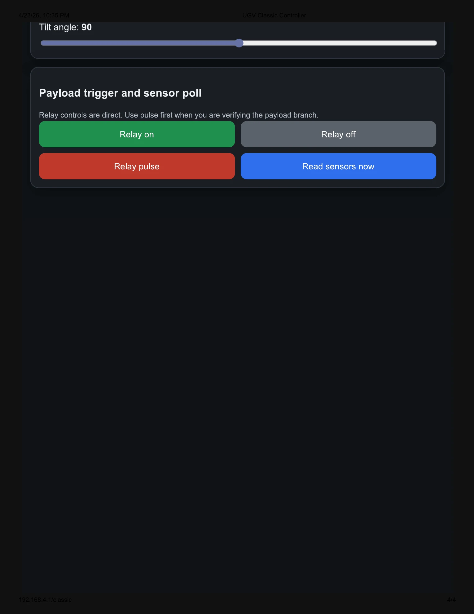
A two-servo payload system provides horizontal and vertical aiming. A relay-controlled payload actuator allows remote triggering from the web interface or Bluetooth controller.
Radar-Style Ultrasonic Sensing
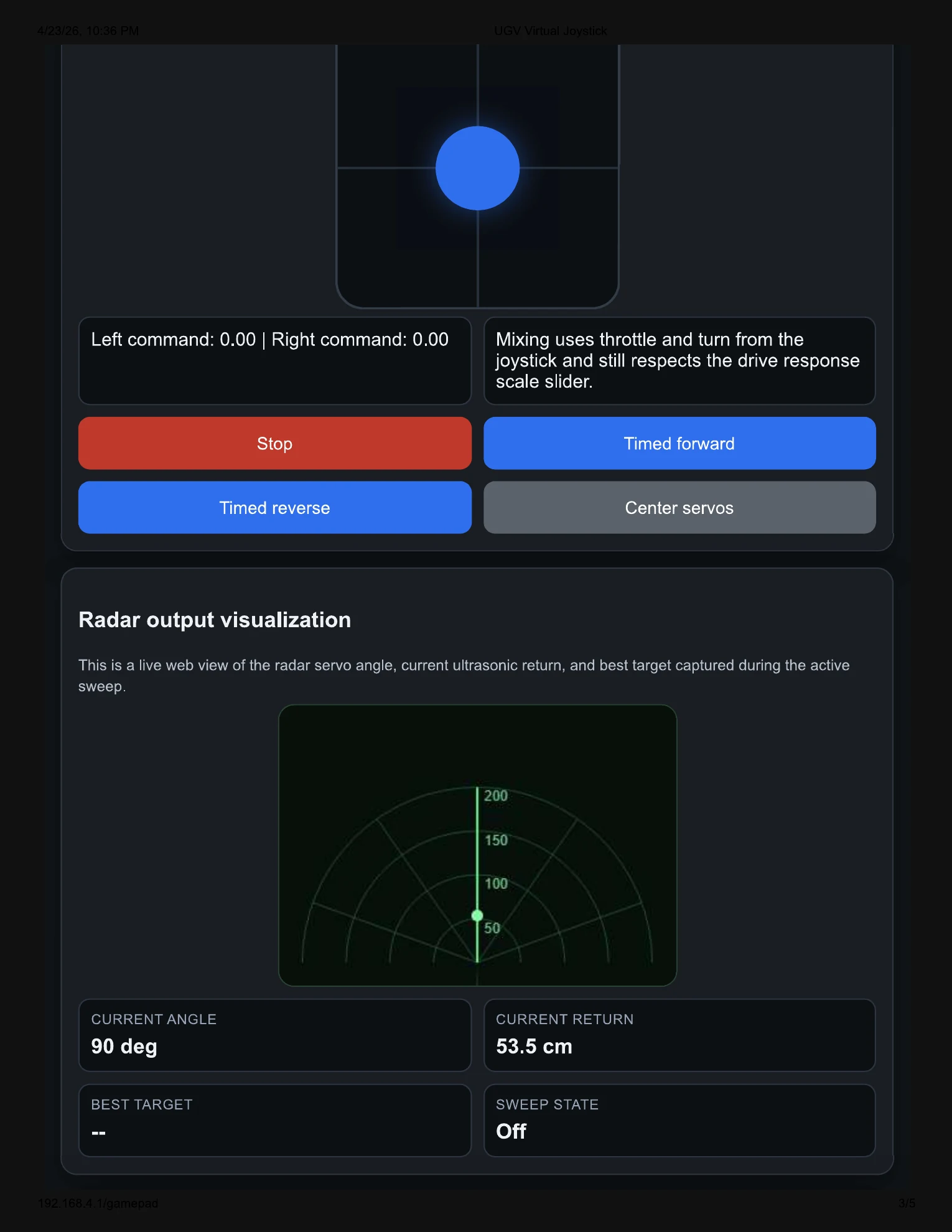
An HC-SR04 ultrasonic sensor mounted on an SG90 servo performs a sweeping scan. Distance data is displayed through the web interface as a radar-style visualization.
Telemetry and OLED Feedback
The rover displays operating status, IP address, control mode, battery telemetry, sensor status, and safety state through the onboard OLED and web interface.
Emergency-Stop Logic
A tilt switch and software emergency-stop latch force the rover into a safe state during rollover events, unsafe orientation, or operator-triggered stop conditions.
Final Hardware Architecture
Core Platform
- Waveshare Wave Rover base platform
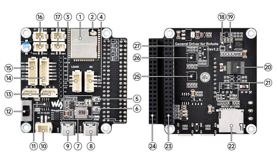
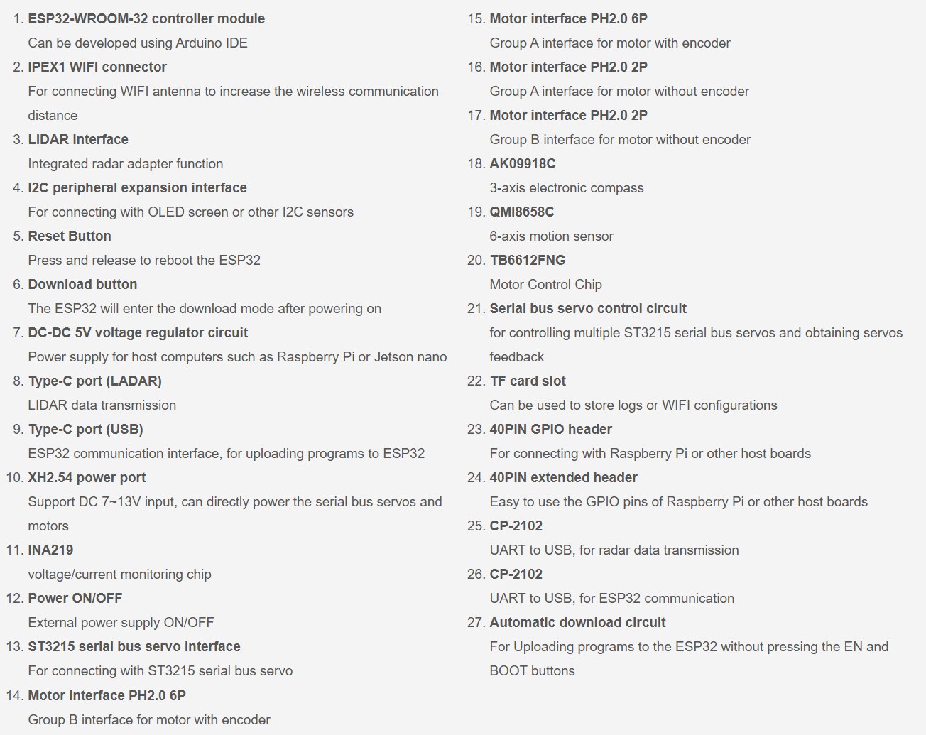
- ESP32-based General Driver for Robots Rev 1.2 board
- 3S 18650 battery system
- External antenna for improved wireless reliability
- OLED display for local status feedback
- Onboard INA219 current/voltage monitoring
Payload and Sensing
- PCA9685 servo driver on the rover I2C bus
- SG90 servo for ultrasonic radar sweep
- Two MG995 servos for payload pan and tilt
- HC-SR04 ultrasonic sensor with voltage divider on the echo line
- Relay-driven payload actuator with separate payload power
- Tilt switch for emergency-stop behavior
Electrical and Control Design
The rover used a split-power approach to improve reliability. Logic power stayed on the rover board, while the servo and relay loads were moved to an accessory 5 V rail with a shared ground reference. This reduced brownout issues caused by servo current spikes and relay/payload transients.
The servo driver, ultrasonic sensor, relay branch, OLED display, and onboard telemetry were integrated around a centralized ESP32-based control system. The public page intentionally keeps the implementation at the architecture level instead of publishing the exact pin map or low-level wiring table.
Peripheral Integration
- Servo driver board added for radar sweep and payload pan/tilt actuation
- Ultrasonic sensing added for front-end distance awareness and radar-style visualization
- Tilt switch added as an emergency-stop safety input
- OLED display used for local status feedback and network information
Payload Control
- Two-servo payload motion supports horizontal and vertical aiming control
- Relay-controlled payload branch separates higher-current actuation from logic control
- Payload testing was performed through both direct debug controls and web-based controls
Power Strategy
- Rover battery powers base platform and logic electronics
- Accessory 5 V rail powers servo and relay-control loads
- Payload motor remains electrically separated on the relay contact side
- Common ground strategy keeps control references consistent across subsystems
Software Architecture
The final firmware was written for the ESP32 using Arduino-style C++. It combined motor control, sensor polling, servo control, web server routes, JSON command handling, Bluetooth gamepad support, persistent boot-mode selection, telemetry reporting, OLED updates, and emergency-stop logic.
Wi-Fi Mode
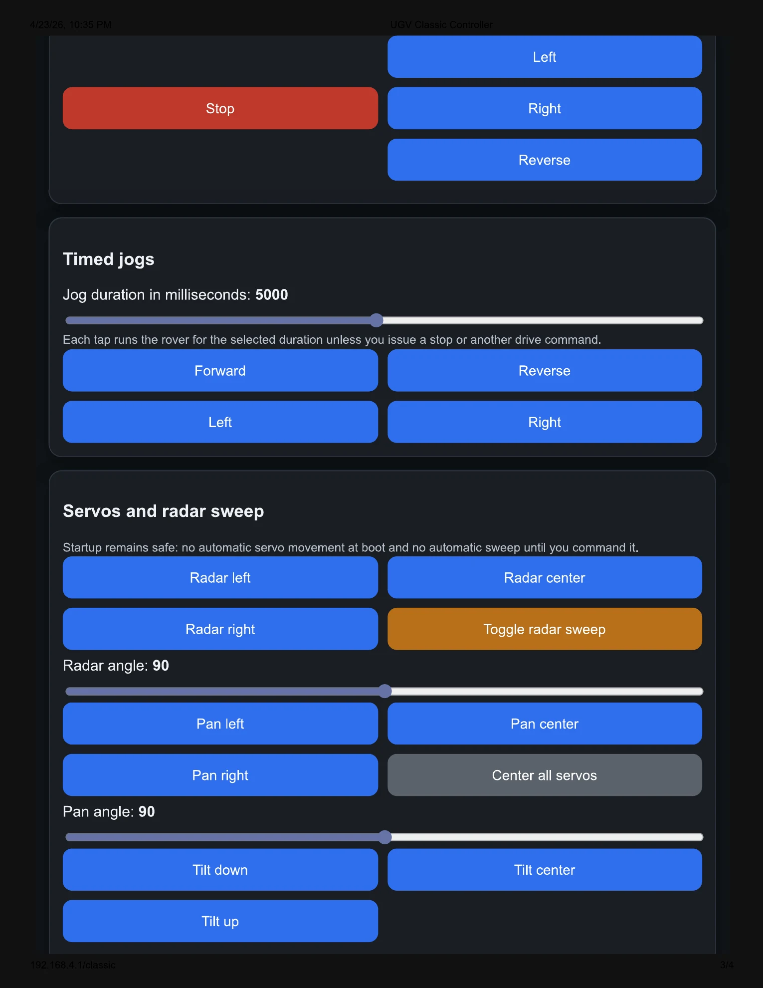
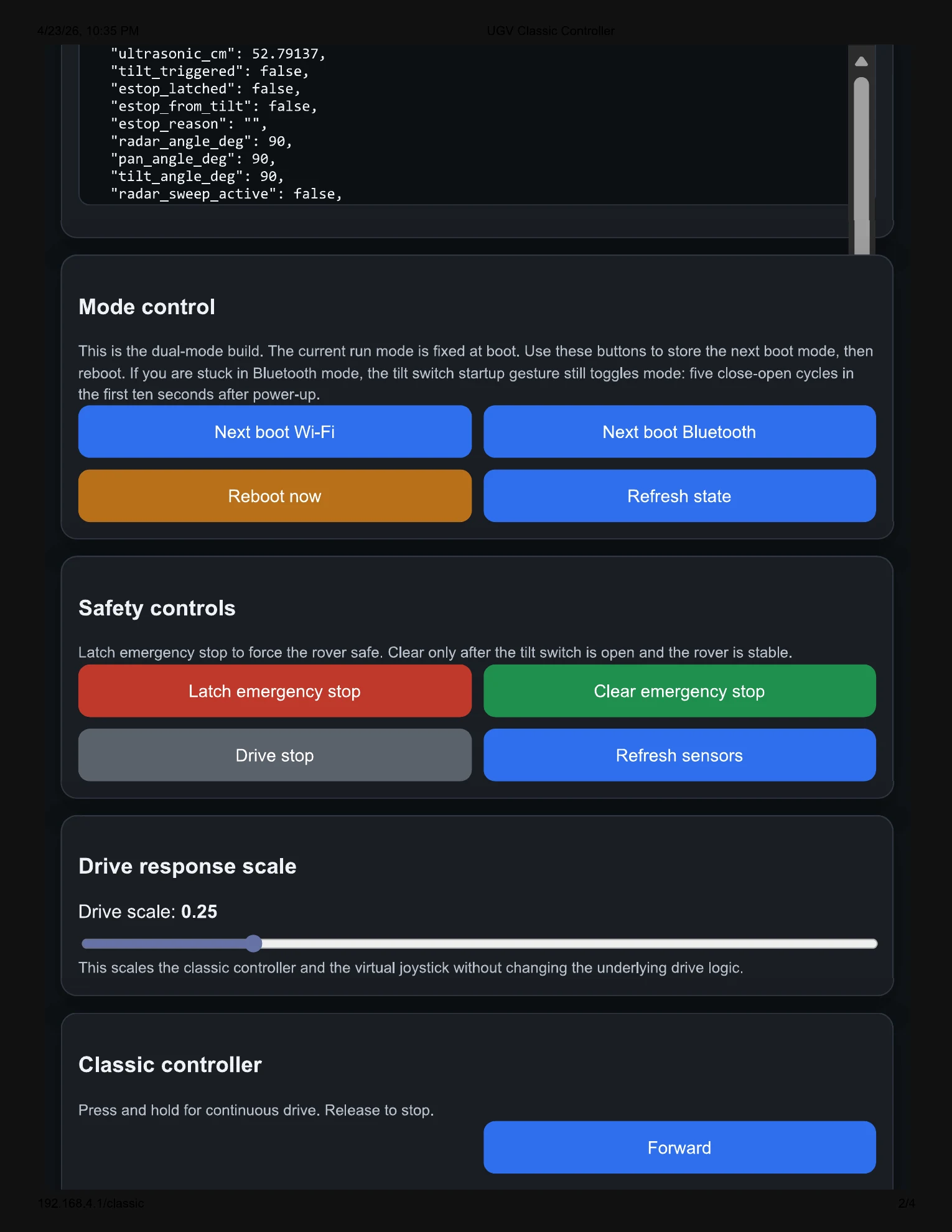
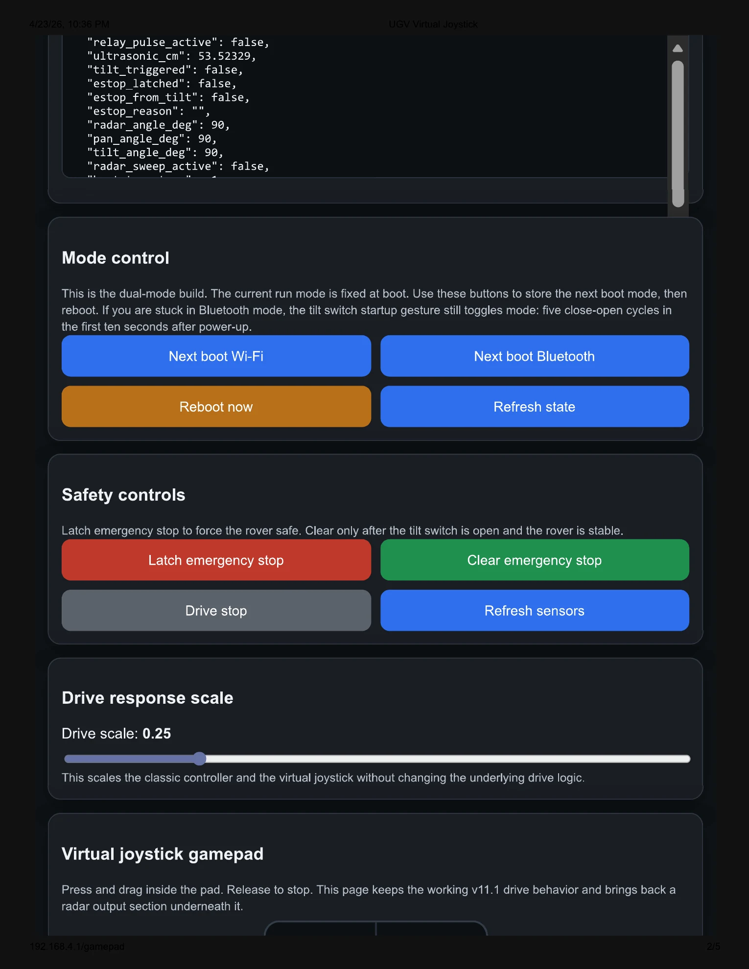
In Wi-Fi mode, the rover becomes a local access point and hosts a control dashboard. The interface includes a home page, classic controller, virtual joystick, radar visualization, servo controls, relay controls, telemetry, and emergency-stop buttons.
Bluetooth Mode
In Bluetooth mode, the rover searches for an Xbox One controller and maps controller inputs to rover movement, payload pan/tilt, radar sweep, payload triggering, and emergency-stop behavior.
Mode Persistence
The firmware stores the next boot mode in nonvolatile preferences. The next mode can be toggled from the web interface, Bluetooth controller, or tilt-switch startup gesture.
Development Progression
Subsystem Bring-Up
Individual testing validated the motors, OLED, ultrasonic sensor, PCA9685 servo driver, relay control, external accessory rail, and tilt switch before full integration.
v10 Full Bring-Up
v10 integrated Wi-Fi access point control, OLED feedback, ultrasonic sensing, servo control, relay control, onboard telemetry, and manual web-based operation.
v11 Interface Expansion
v11 improved the user interface by separating the system into a home page, classic controller page, and virtual joystick page while preserving the working backend behavior.
v11.11 Final Demo Build
v11.11 added the final dual-mode Wi-Fi/Bluetooth architecture, Xbox controller support, radar visualization, payload controls, startup mode selection, and emergency-stop behavior used for the final demonstration.
Engineering Challenges
Power Stability
Servo and relay loads caused brownout risk when powered from weak or shared rails. The solution was to separate accessory power from logic power while keeping all control grounds common.
Pin Conflicts
Several ESP32 pins had board-level functions or serial conflicts. The final pin map was selected after testing which pins could support sensors and peripherals without upload or serial issues.
Control Latency
Blocking sensor reads affected web responsiveness. Later firmware revisions reduced blocking behavior, shortened ultrasonic timeouts, and prioritized control responsiveness.
Integration Scope
The project required simultaneous mechanical mounting, wiring, firmware, user interface, safety behavior, payload control, and live testing under a tight course-project timeline.
Results
The final MAG-V prototype demonstrated remote rover motion, browser-based control, Bluetooth gamepad operation, payload aiming, payload triggering, ultrasonic radar-style sensing, OLED status display, onboard telemetry, and emergency-stop behavior. The system was successfully demonstrated as a modular ground-vehicle platform with room for future autonomy and sensor-fusion development.
Validated Capabilities
- Wi-Fi access point control from a mobile browser
- Classic button control and virtual joystick control
- Bluetooth gamepad driving and payload control
- Radar-style ultrasonic sweep visualization
- Payload pan/tilt servo control
- Relay-based payload actuation
- OLED telemetry and status feedback
- Tilt-triggered and software emergency stop behavior
Future Improvements
- Add autonomous navigation and obstacle avoidance
- Improve radar visualization and data logging
- Add cleaner enclosure and cable-management hardware
- Publish cleaned firmware modules
- Add rover photos, demo clips, and wiring diagrams to this page
- Expand IMU-based motion analysis and sensor fusion
Hardware Integration Summary
The MAG-V platform integrates drivetrain control, servo-based payload positioning, ultrasonic sensing, onboard telemetry, emergency-stop logic, and web-based operator control through a centralized ESP32-based control architecture. This public summary focuses on the system architecture and engineering decisions rather than publishing the full implementation pin map.
Control Electronics
The rover uses an ESP32-based driver board as the central controller for drivetrain commands, local telemetry, wireless communication, and peripheral coordination.
Sensor and Telemetry Layer
The system includes ultrasonic range sensing, onboard battery monitoring, OLED status output, and safety input handling for operator feedback during testing and demonstration.
Payload and Actuation Layer
A servo driver board coordinates the radar sweep servo and payload pan/tilt servos, while a relay-controlled payload branch keeps higher-current actuation separate from logic control.
Power-Domain Separation
Logic, servo, and payload power paths were separated where practical to reduce brownouts, protect the controller, and improve reliability during subsystem testing.
Detailed wiring tables, pin assignments, firmware, and low-level build notes are kept out of the public page and reserved for private documentation, controlled project handoff, or technical review.
Project Media and Documentation
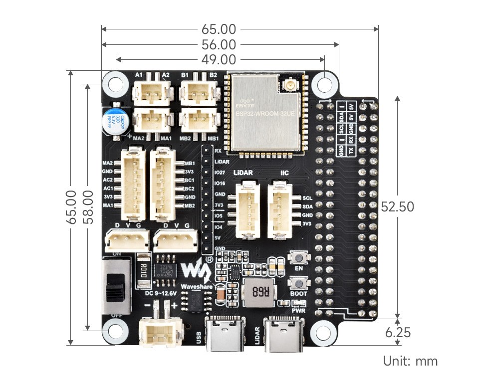
The media below focuses on the final demonstration configuration, payload planning, dimensional references, electrical documentation, CAD references, and embedded web interface screenshots. Extra platform photos are being kept offline for now while the public-facing project media is refined.
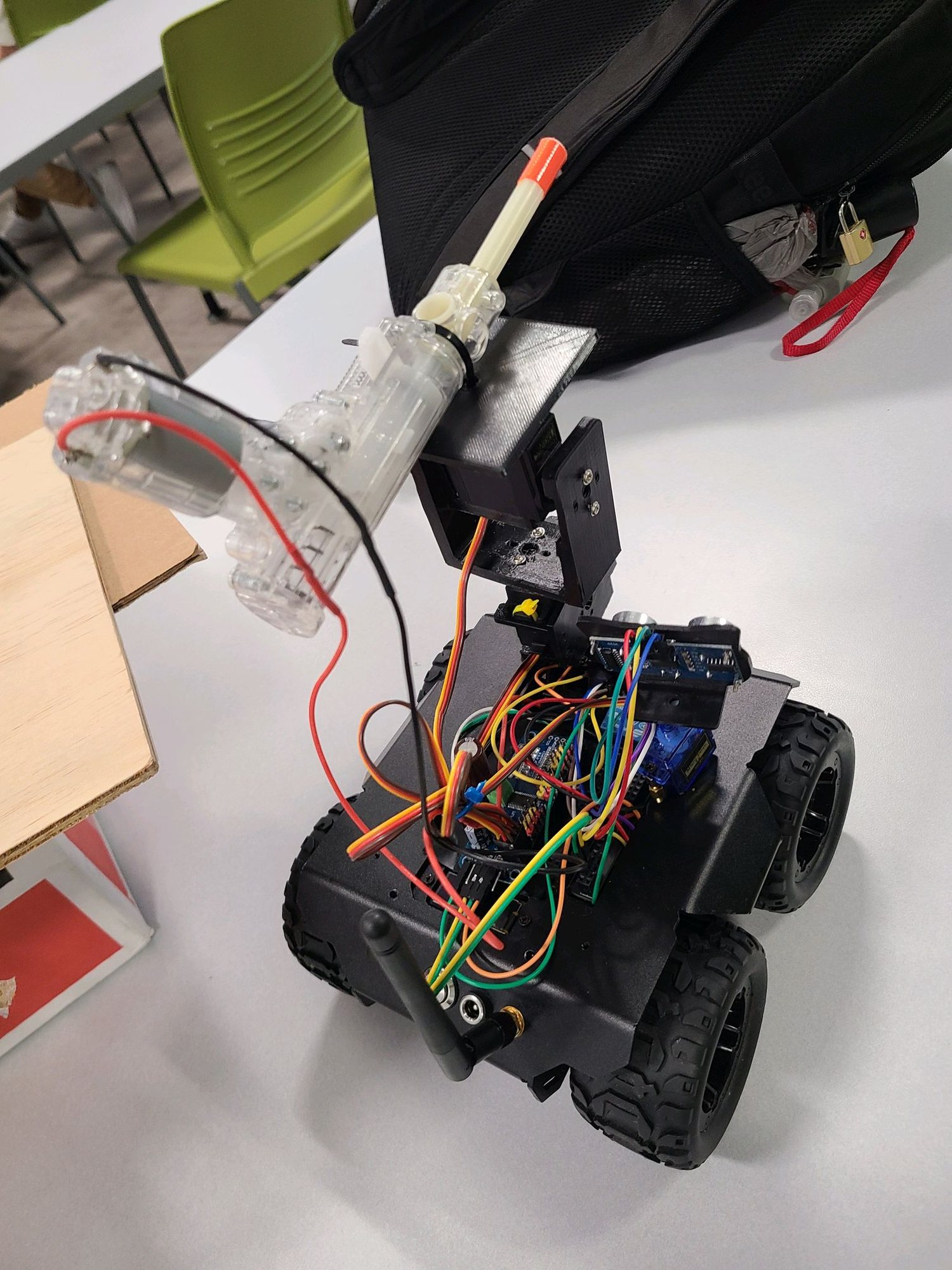
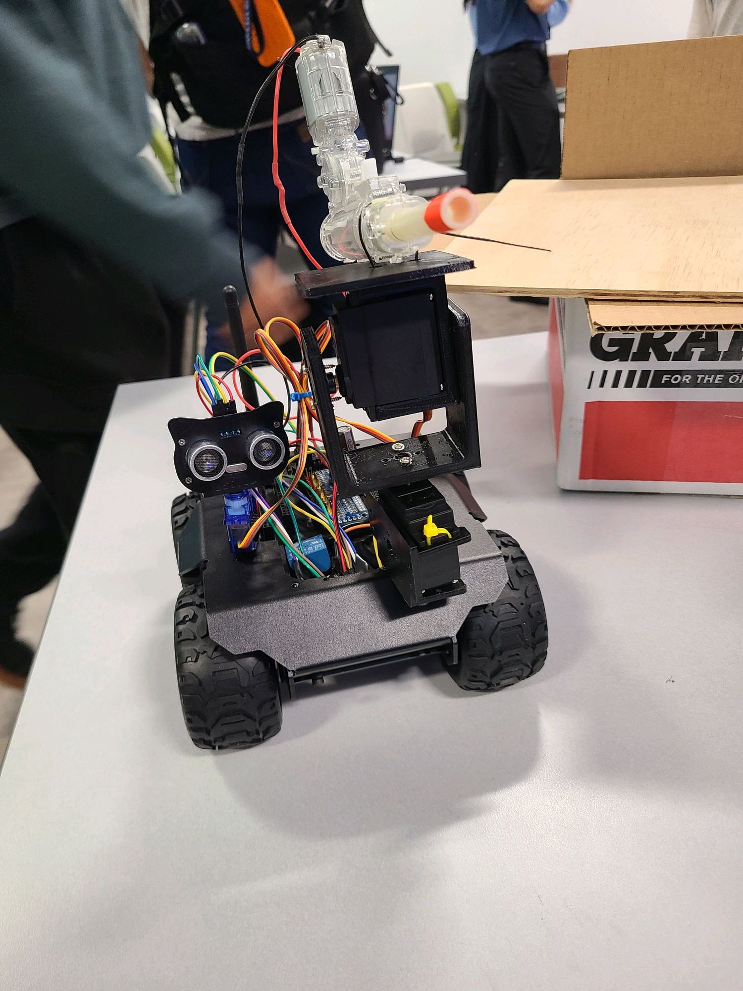
Final Demonstration Configuration
These selected views document the rover in its final demonstration configuration without publishing the full raw photo set.

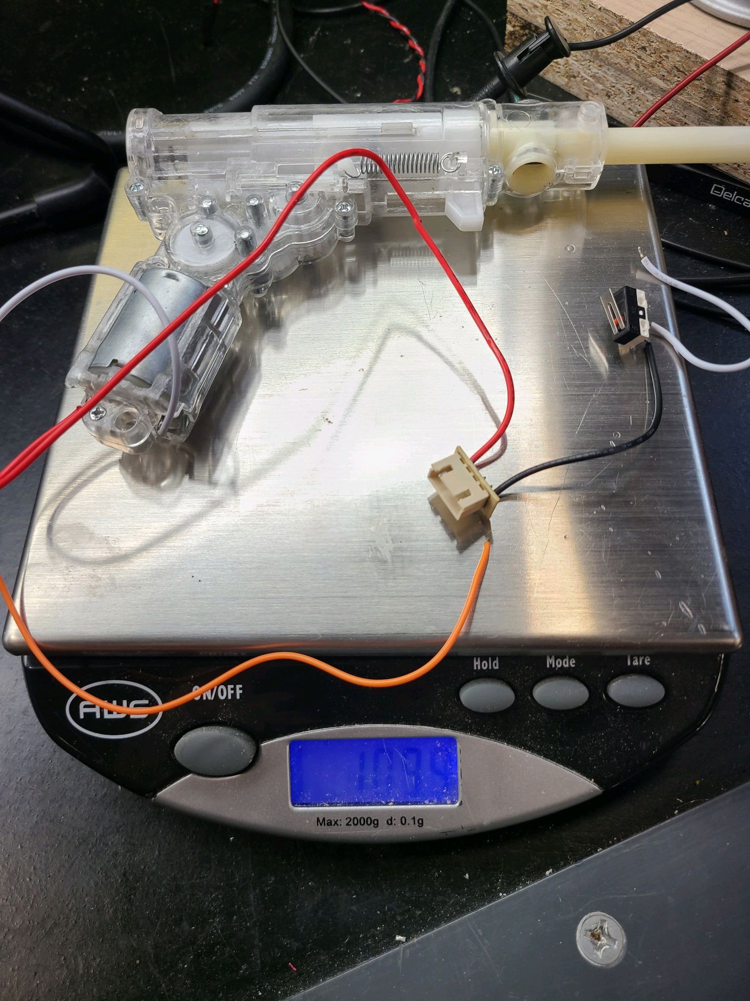
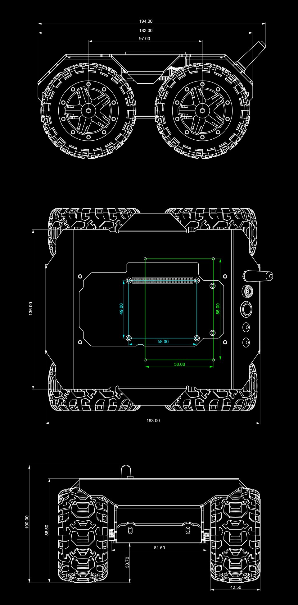
Payload Mechanism and Mechanical Planning
The payload module used a two-servo pan/tilt concept and a separate relay-actuated payload branch. The public media here focuses on the payload mass check and CAD reference material rather than internal concept sketches.
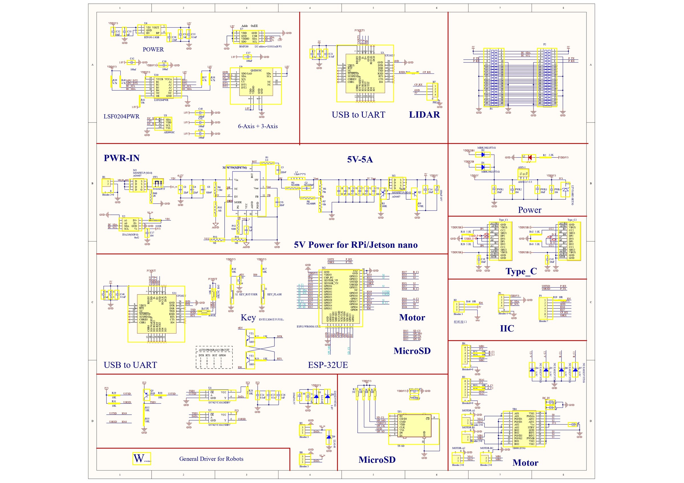
Electrical and System Documentation
Electrical documentation was used to track the ESP32 driver board, PCA9685 servo driver, ultrasonic sensor, relay payload circuit, shared ground strategy, and accessory power domains. The public-facing page keeps the manufacturer board references and higher-level diagrams visible while omitting internal wiring-note screenshots.
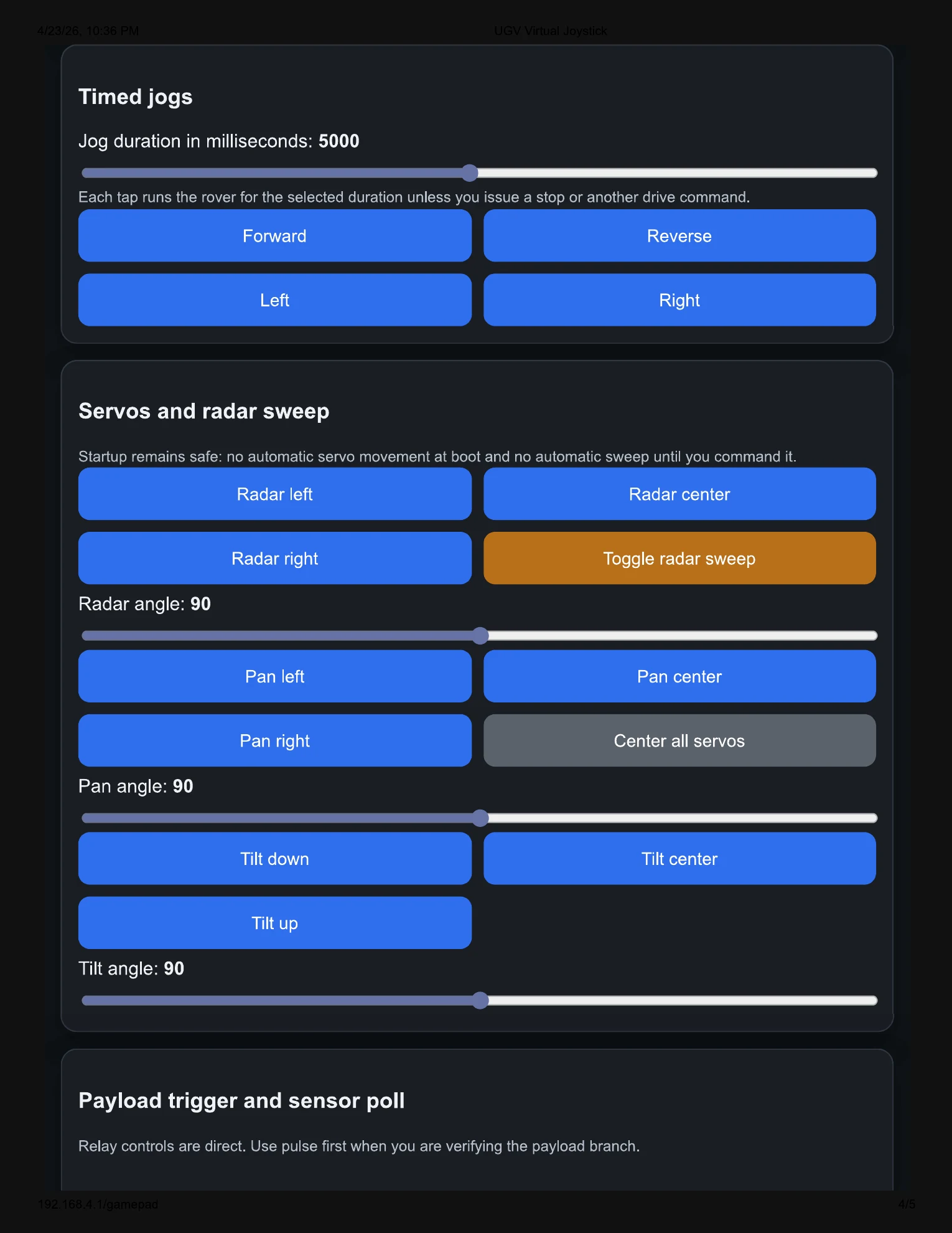
Embedded Web Interface
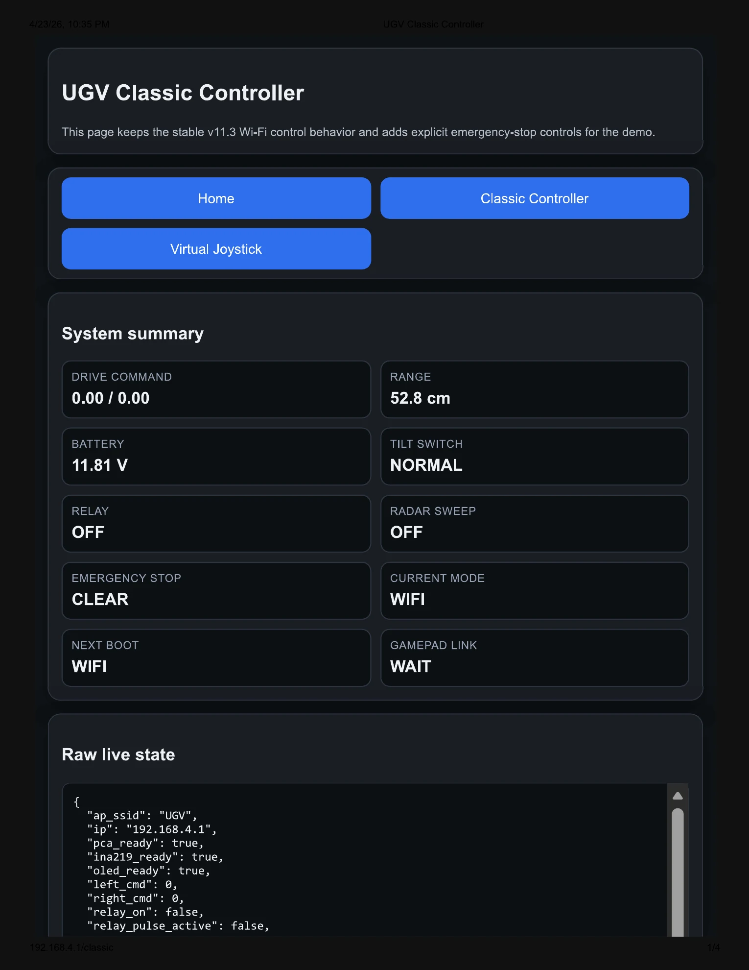
The MAG-V web interface was built directly into the rover firmware and served from the ESP32 over the rover's local Wi-Fi access point. The interface included a home/status page, a classic controller, a virtual joystick controller, live telemetry, radar-style ultrasonic visualization, payload controls, servo controls, and emergency-stop controls.
View full web UI export gallery


Note: this page is a cleaned public-facing technical summary of a Mechatronics project. Course submission files, private links, full code appendices, and raw reference materials are intentionally not published.
References and Resources
These references supported manufacturer documentation review, hardware understanding, and Waveshare rover software-architecture research. Inclusion here does not imply that any code or design work was copied directly from these sources.
Manufacturer Documentation
Official Waveshare Software Reference
Acknowledgements
I thank Dr. Hussain Rizvi and the Department of Mechanical Engineering at the University of Texas at Tyler for project guidance, resources, and use of the Ratliff Engineering Laboratory facilities.
Related Work / Contact
This project connects directly to my broader work in embedded systems, robotics, CAD, data acquisition, power systems, and electromechanical prototyping.