Project Overview
Splash Force was a 2-liter water rocket design project completed under competition-style constraints. The goal was to design, fabricate, calibrate, and test a bottle rocket capable of stable flight, improved altitude, and increased hang time.
The final design used a lightweight parabolic PLA nose cone, clipped-delta fins, added nose ballast, and experimental stability calibration to improve flight behavior. The work combined CAD modeling, MATLAB trajectory simulation, Autodesk CFD visualization, 3D printing, physical calibration, and flight testing.
Recognition
Splash Force received third place in the school-wide water rocket competition. I also received a participation certificate for the project. Both certificates were issued by the College of Engineering and signed by the Dean of the College of Engineering.
The final stabilized design achieved a measured height of 40 m, flight duration of 5.12 s, velocity of 34 m/s, and experimental stability margin of 1.1 calibers.
My Role
I served as team leader for this water-rocket design project. My primary responsibilities included coordinating the final project direction, writing the final design report, developing the MATLAB simulation code, creating the Autodesk CFD simulation work, fabricating the 3D-printed rocket components, and integrating the subsystem work into a complete engineering documentation package.
The project included assigned subsystem responsibilities across stability, fin design, nose cone design, and materials research. I supported the overall design integration by connecting those subsystem inputs into the final CAD, simulation, fabrication, calibration, testing, and reporting workflow.
Team Context
Subsystem Roles
- Team lead and final integration: Jake Cummings
- Stability analysis: Sunday Aina
- Fin design: Ethan Tran
- Nose cone design: Binh Duong
- Materials research: Christopher Anaghan
My Contributions
- Served as team leader
- Wrote the final design report
- Developed the MATLAB projectile-motion and sweep simulation code
- Created the Autodesk CFD simulation work
- Fabricated the 3D-printed nose cone and fin components
- Integrated CAD, simulation, fabrication, calibration, testing, and results into the final documentation package
Testing Results
Final testing showed improved velocity, altitude, flight duration, and stability compared with the unstabilized prototype.
| Measurement | Unstabilized Prototype | Stabilized Prototype | Percent Change |
|---|---|---|---|
| Velocity | 21.2 m/s | 34 m/s | 61.1% |
| Height | 36.4 m | 40 m | 9.89% |
| Duration | 3.43 s | 5.12 s | 49.3% |
| Stability Margin | N/A | 1.1 Cal | Stable final configuration |
Technical Summary
The project followed a complete engineering workflow from concept and subsystem research through simulation, fabrication, calibration, and final flight testing.
Aerodynamic Design
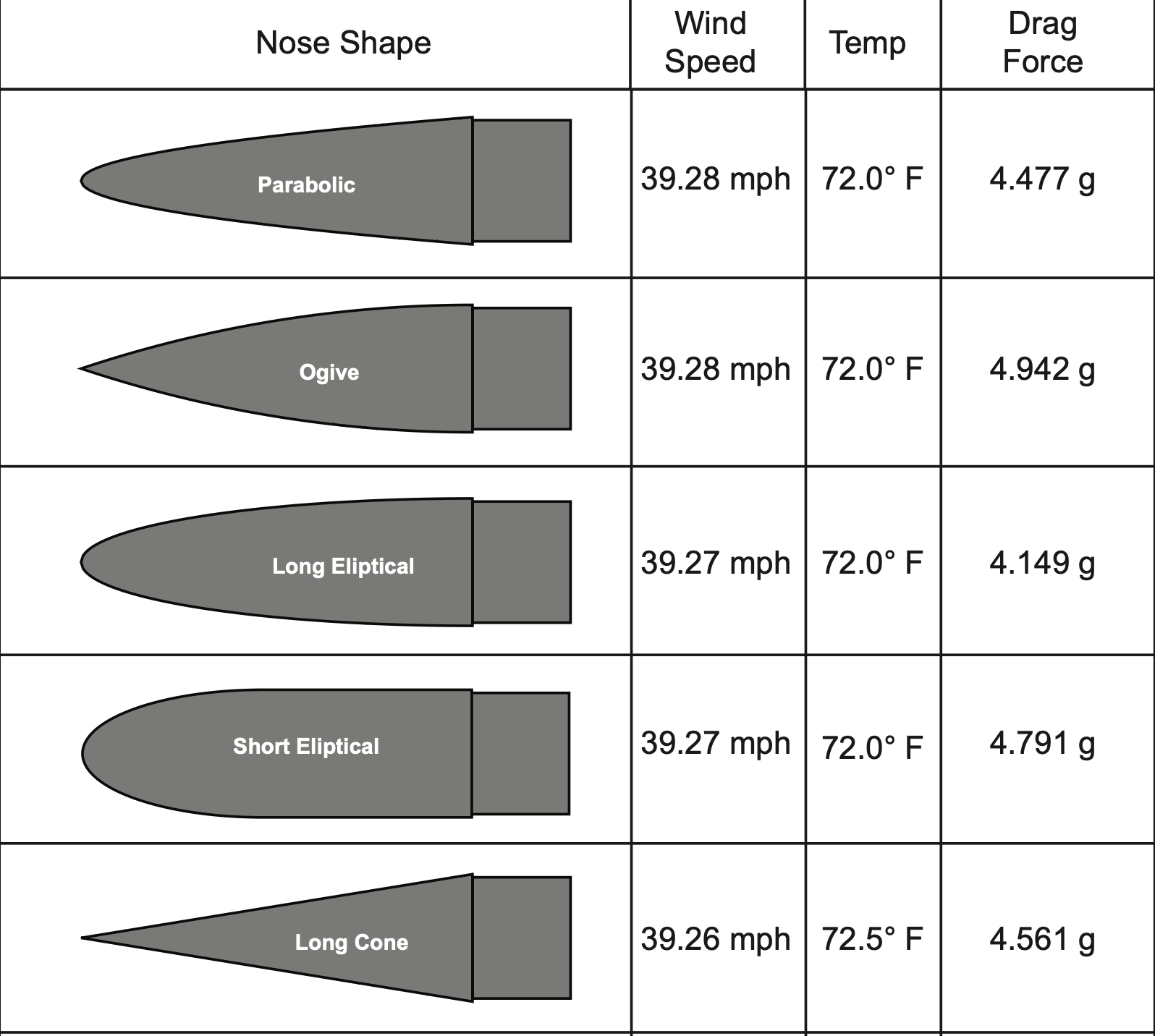
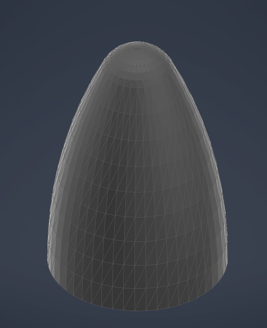
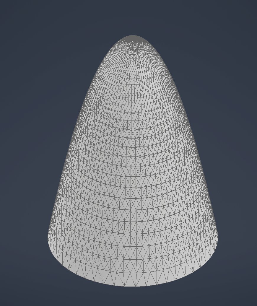
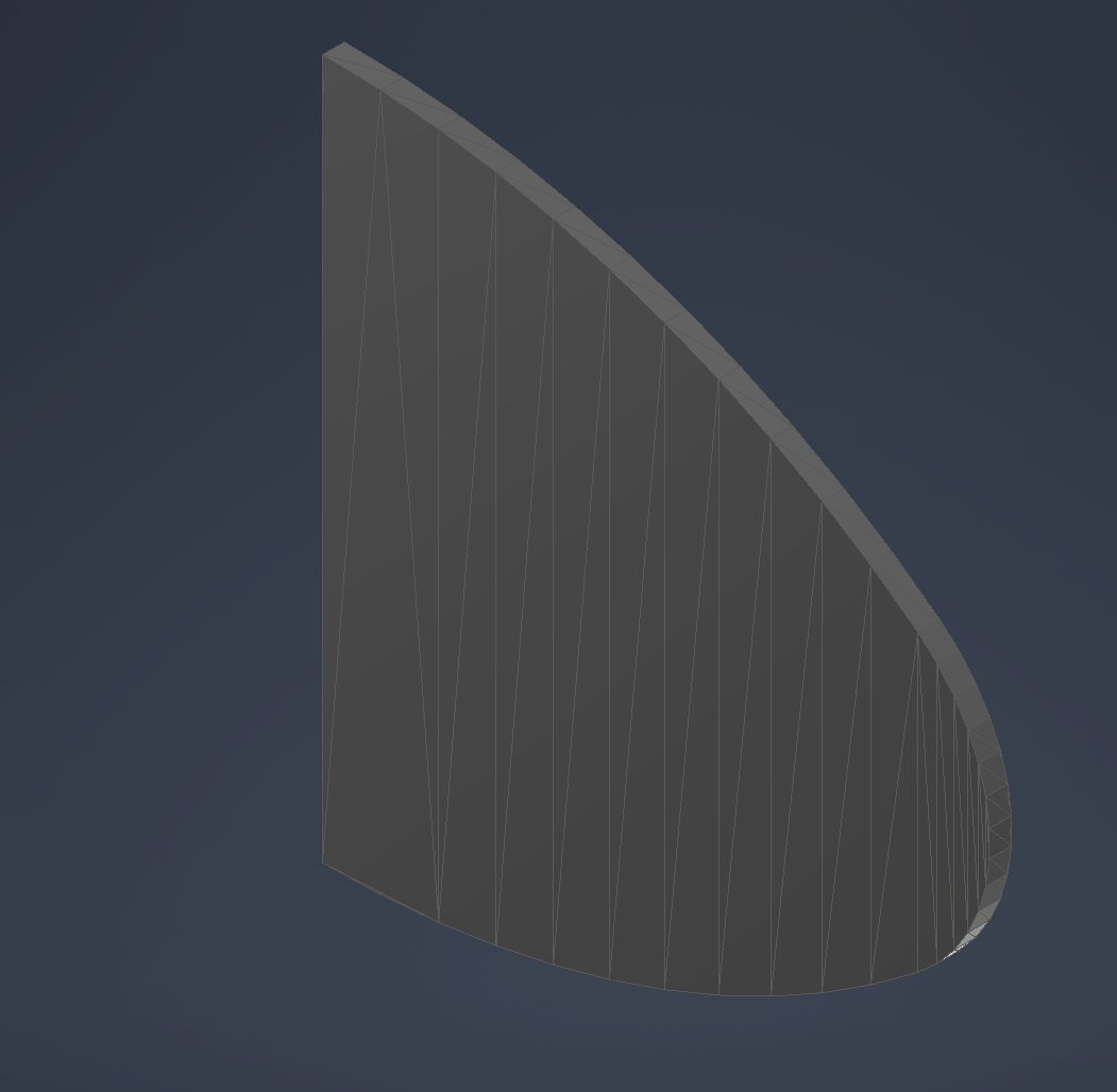
The rocket used a parabolic nose cone to reduce drag and improve airflow over the body. The cone was designed as a lightweight PLA shell with tapered wall thickness.
Fin Design
The final fin configuration used a clipped-delta shape selected for stability, bonding area, manufacturability, and drag reduction.
Trajectory Simulation
MATLAB was used to model projectile motion, air-drag behavior, pressure sweep effects, and expected flight trajectories across multiple launch conditions.
CFD Simulation
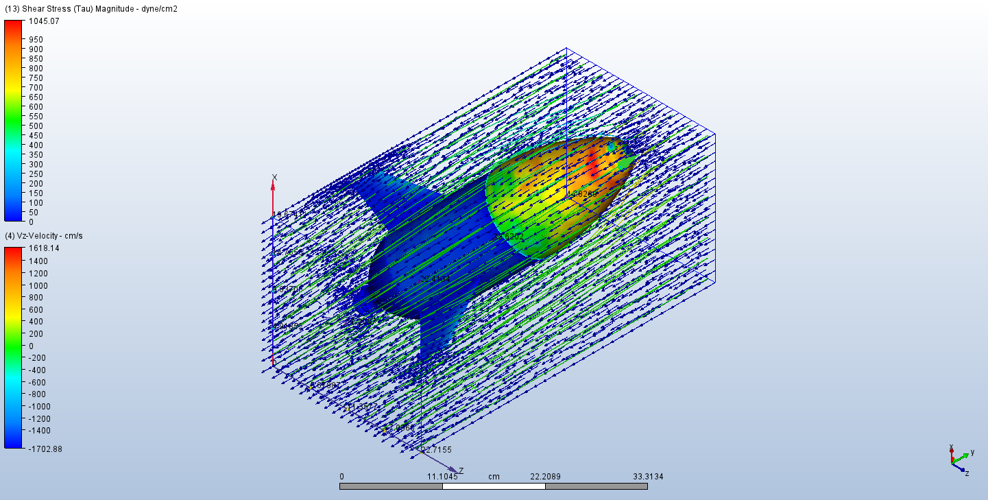
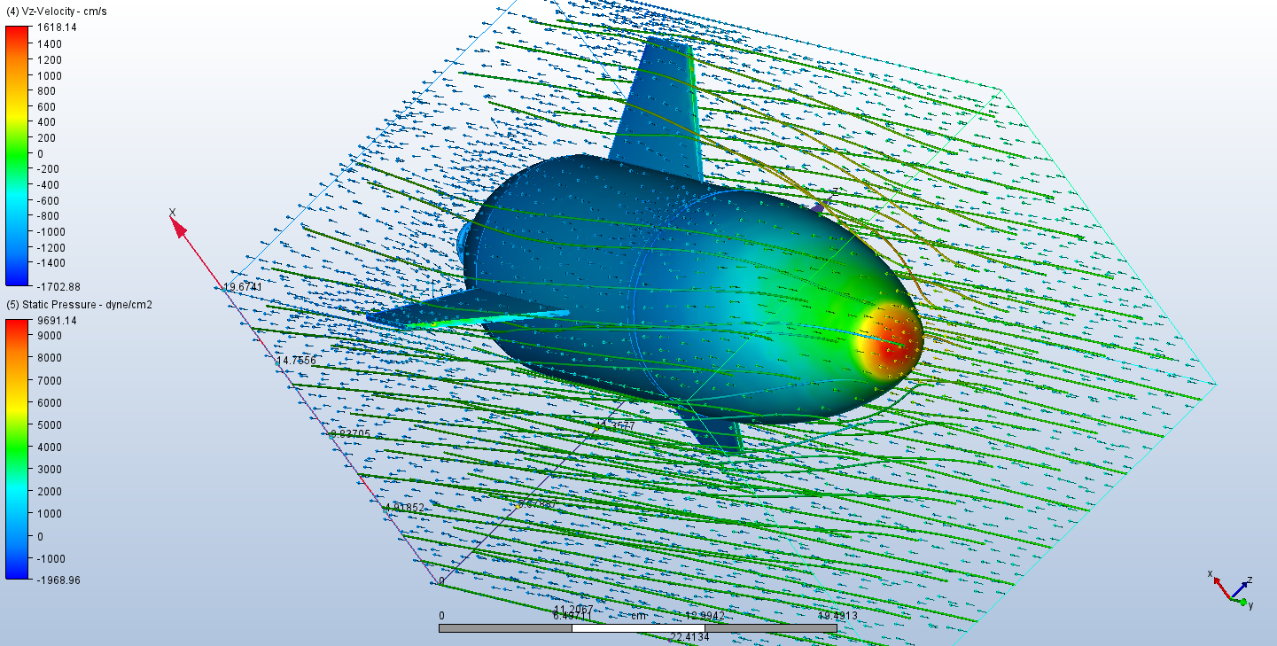
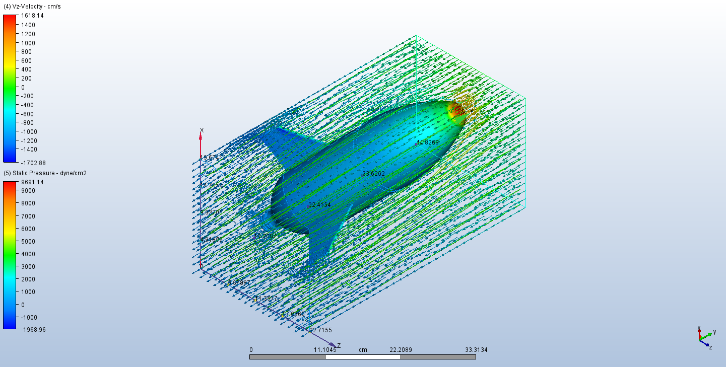
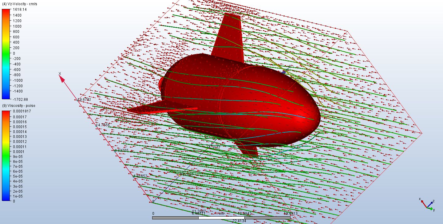
Autodesk CFD was used to visualize airflow behavior, static pressure distribution, shear stress, and velocity fields around the rocket model.
Design and Fabrication
Nose Cone
- Parabolic geometry selected for low drag
- 3D printed using lightweight PLA filament
- Approximate length: 6.2 in
- Tapered wall thickness from about 0.03 in to 0.02 in
- Designed to support nose ballast for center-of-mass tuning
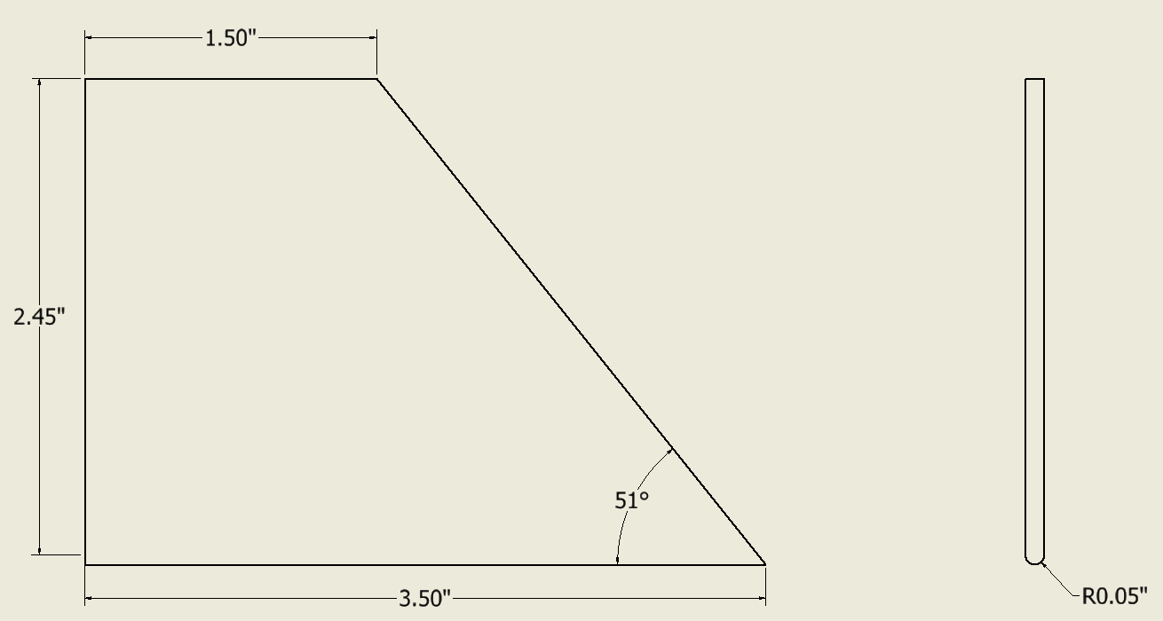
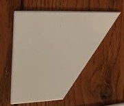
Fins
- Final shape: clipped delta
- Material: PLA filament
- Designed for bonding surface area and reduced drag
- Final fin area reported as 6.125 in²
- Used to improve static stability and flight direction
Calibration and Stability
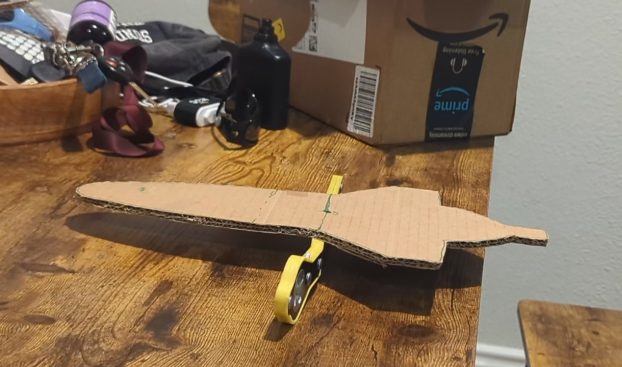
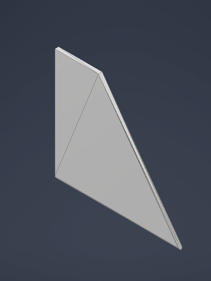
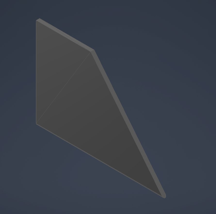
Rocket stability was evaluated using center of pressure, center of mass, body diameter, and stability margin in calibers. The team used a geometrically identical 2D cardboard projection of the final rocket design to support the center-of-pressure estimate, then compared that result against the measured center of mass after ballast was added near the nose.
Center of Pressure
Center of pressure was estimated using a silhouette-based area and centroid method. The 2D cardboard projection helped preserve the final rocket outline while simplifying the geometric calculation.
Center of Mass
Center of mass was measured on the physical rocket and adjusted using ballast added near the nose cone to improve flight stability.
Final Experimental Stability
The final stabilized configuration achieved an experimental stability margin of 1.1 calibers, placing it in the stable range.
Stability Analysis Media
These images document the physical stability-check workflow: comparing the final rocket geometry to a geometrically similar 2D projection, then using the physical assembly to support center-of-mass and center-of-pressure reasoning.
Design, CAD, and Fabrication Media
Project visuals organized to follow the final presentation sequence: project identity, overall CAD layout, nose-cone development, fin development, fabrication details, fabrication issues, and final build views.
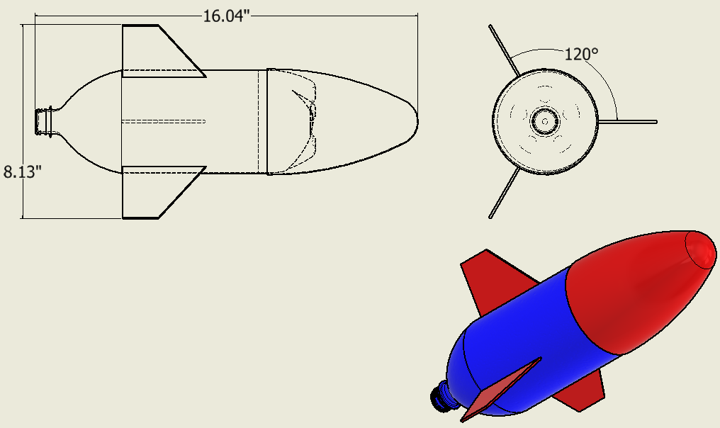
Project Identity and Overall CAD Layout
The presentation opened with the Splash Force identity and then moved into the overall rocket layout, showing the approximate body length, fin placement, nose-cone geometry, and assembled CAD concept.
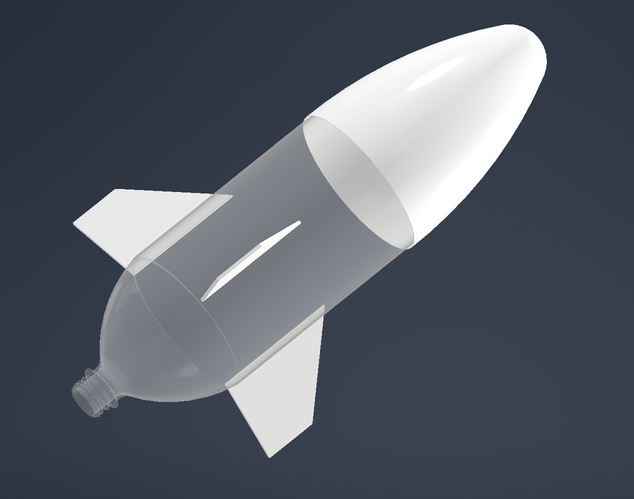
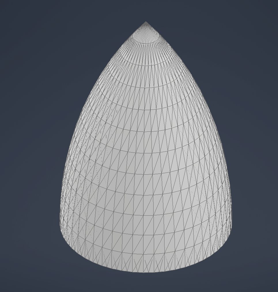
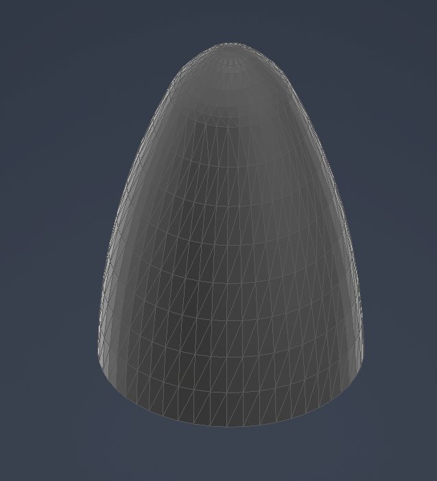
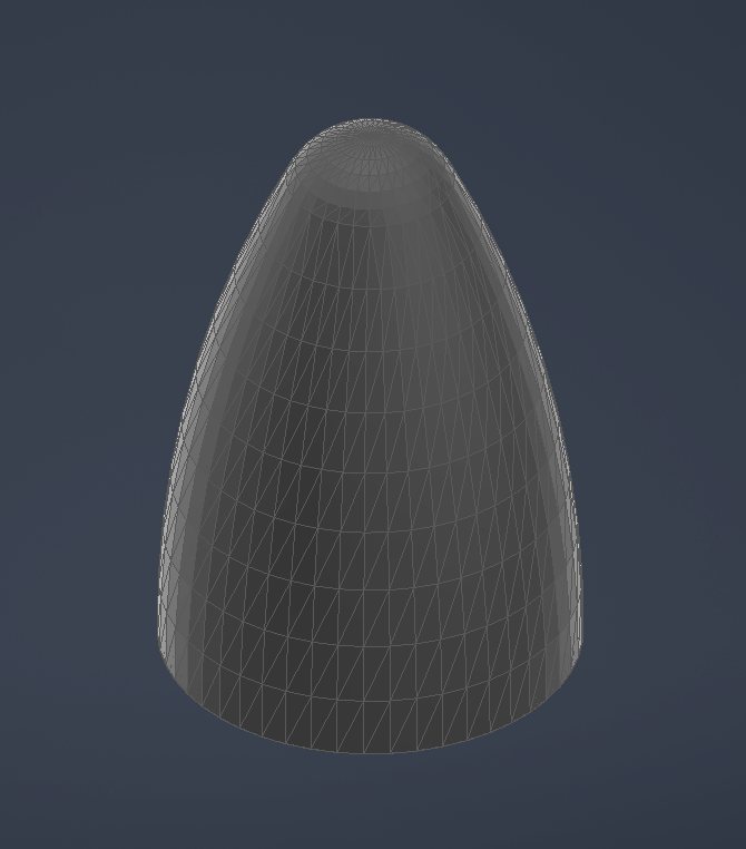
Nose Cone Development
The nose cone was selected as a parabolic, lightweight PLA component to reduce drag while leaving room for ballast near the tip. The development process included technical drawing, print validation, and multiple geometry revisions before the final printed part.
Nose-Cone Revision Set
Fin Design
The clipped-delta fin was selected for a practical balance of stability, bonding surface area, manufacturability, and drag reduction compared with other fin concepts.
Fin Revision Set
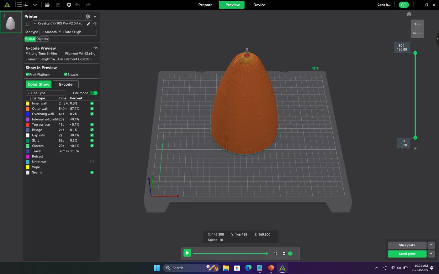
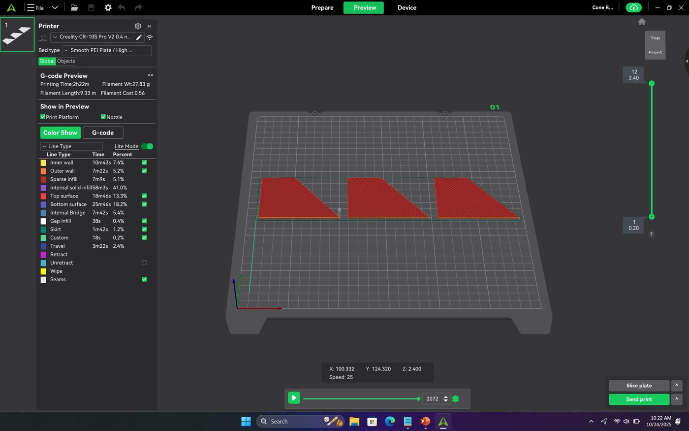
Fabrication Details
Fabrication work included preparing print orientations, checking slicer previews, printing the nose cone and fins, and integrating the printed parts onto the 2-liter bottle body.
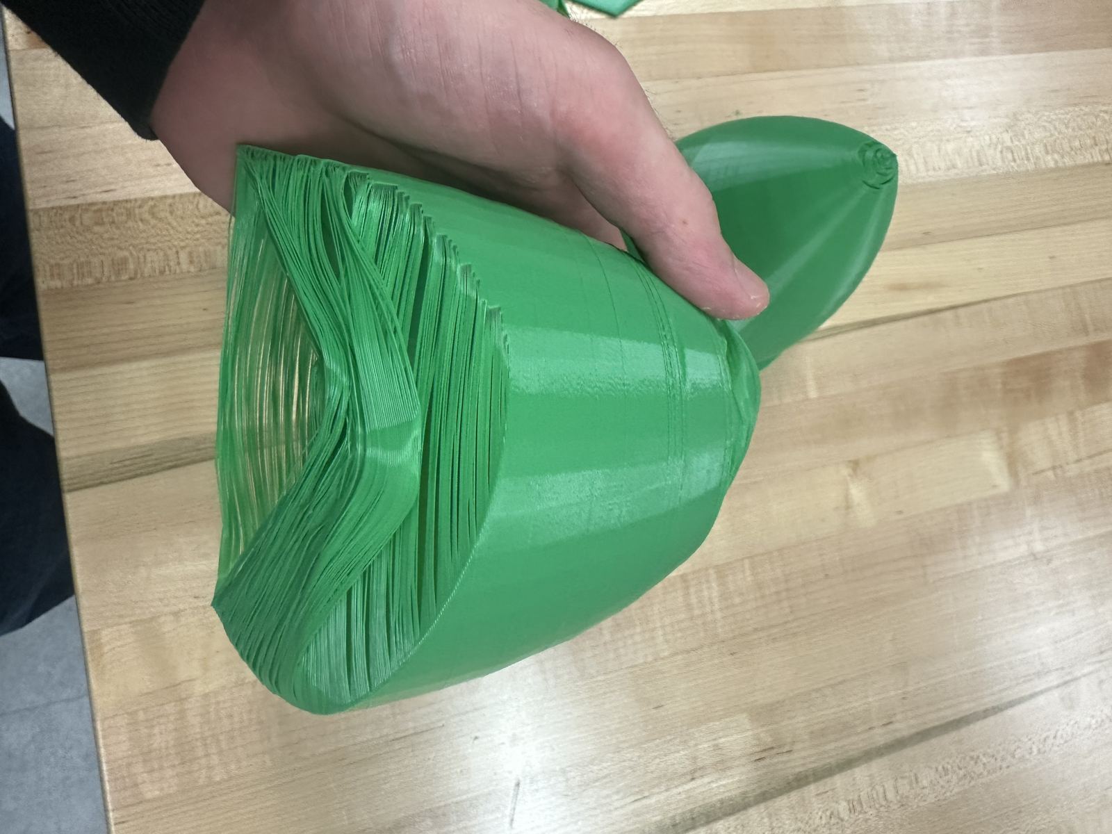
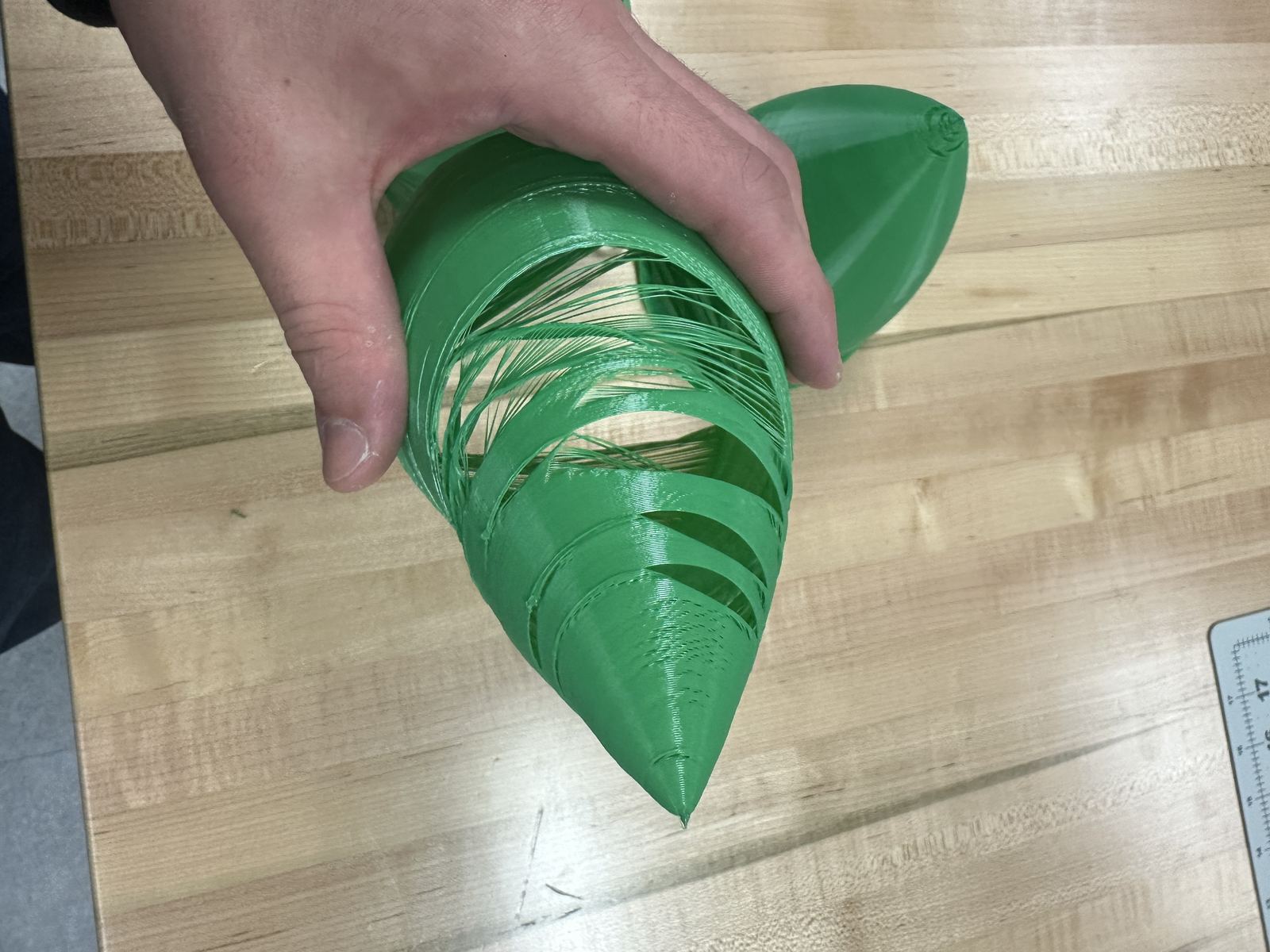
Fabrication Issues Encountered
These photos document print and handling issues encountered during fabrication. They are included because they show the real iteration work behind the final printed nose-cone component.
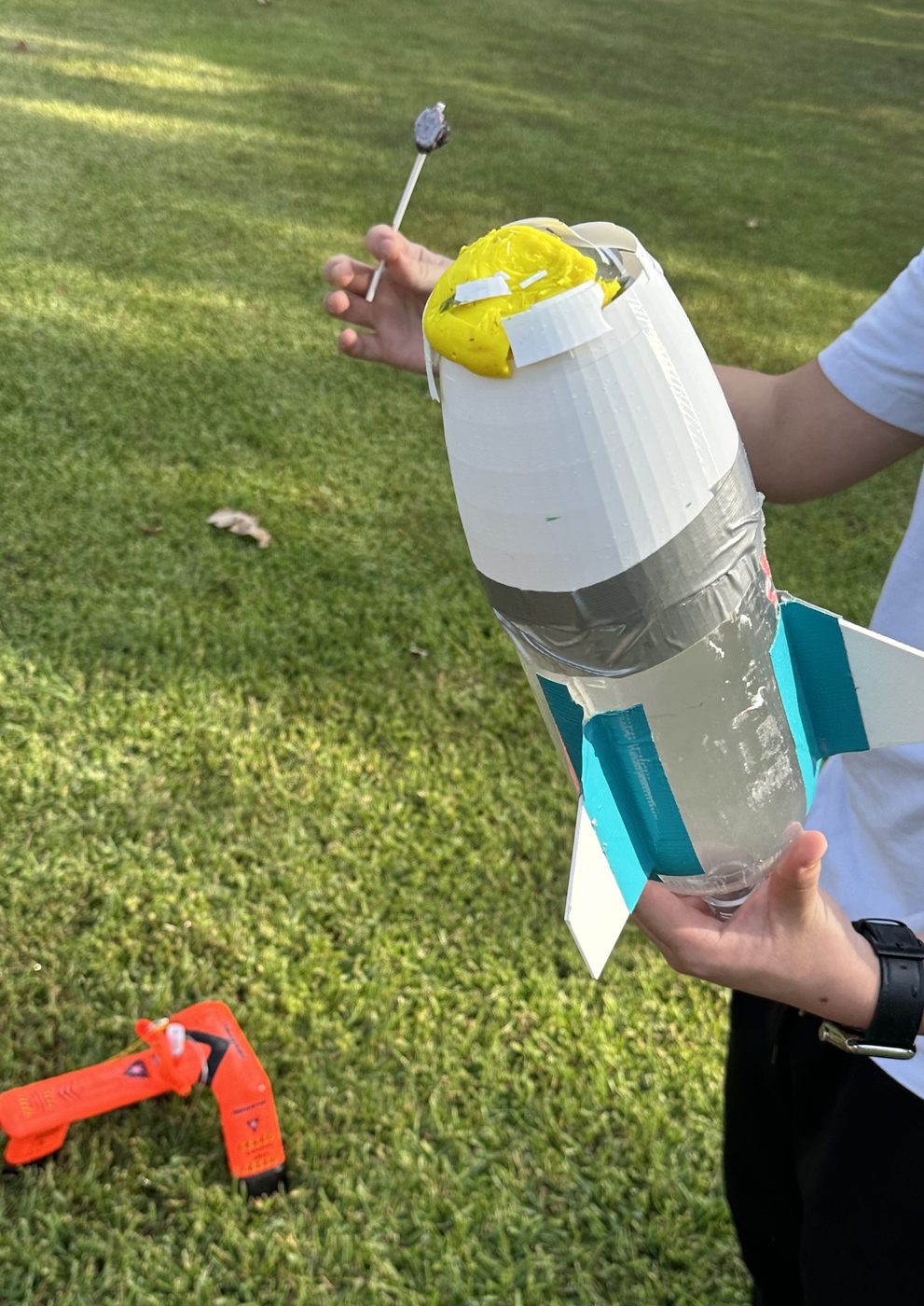
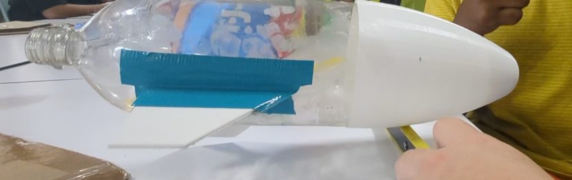
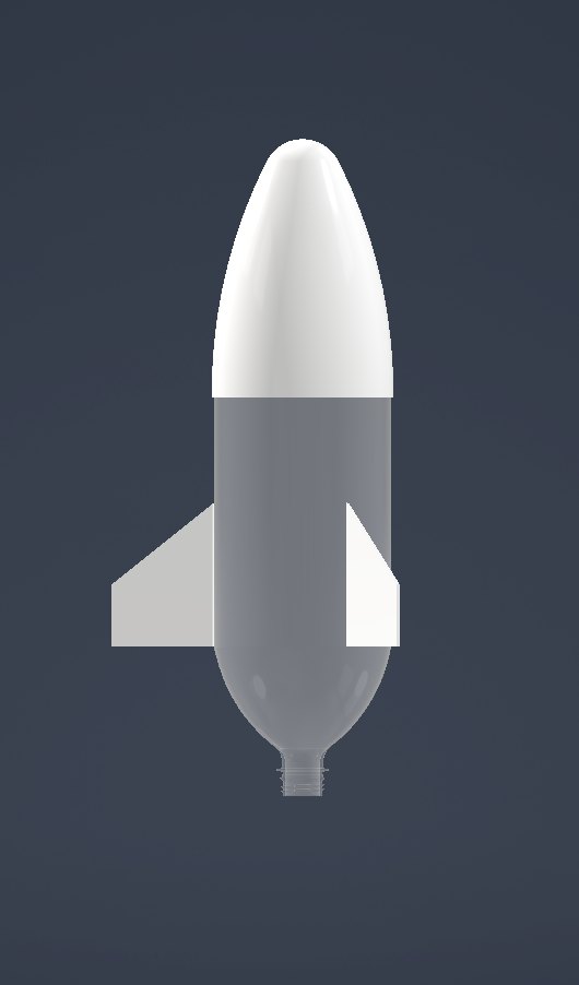
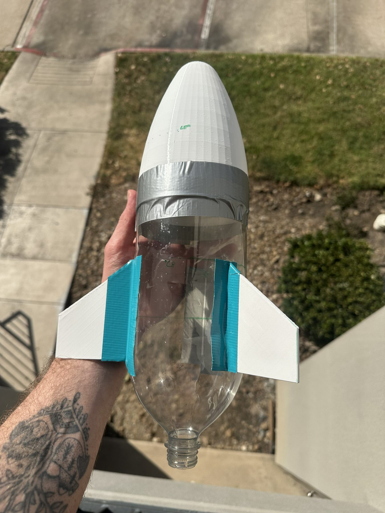
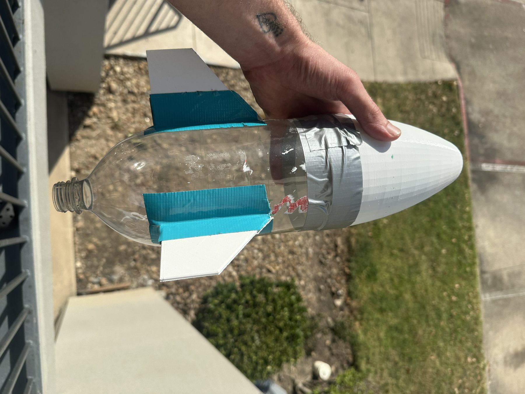
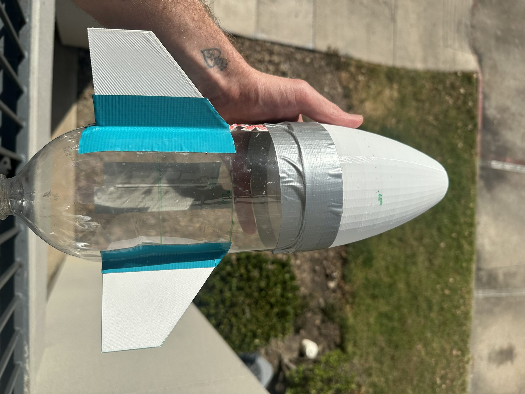
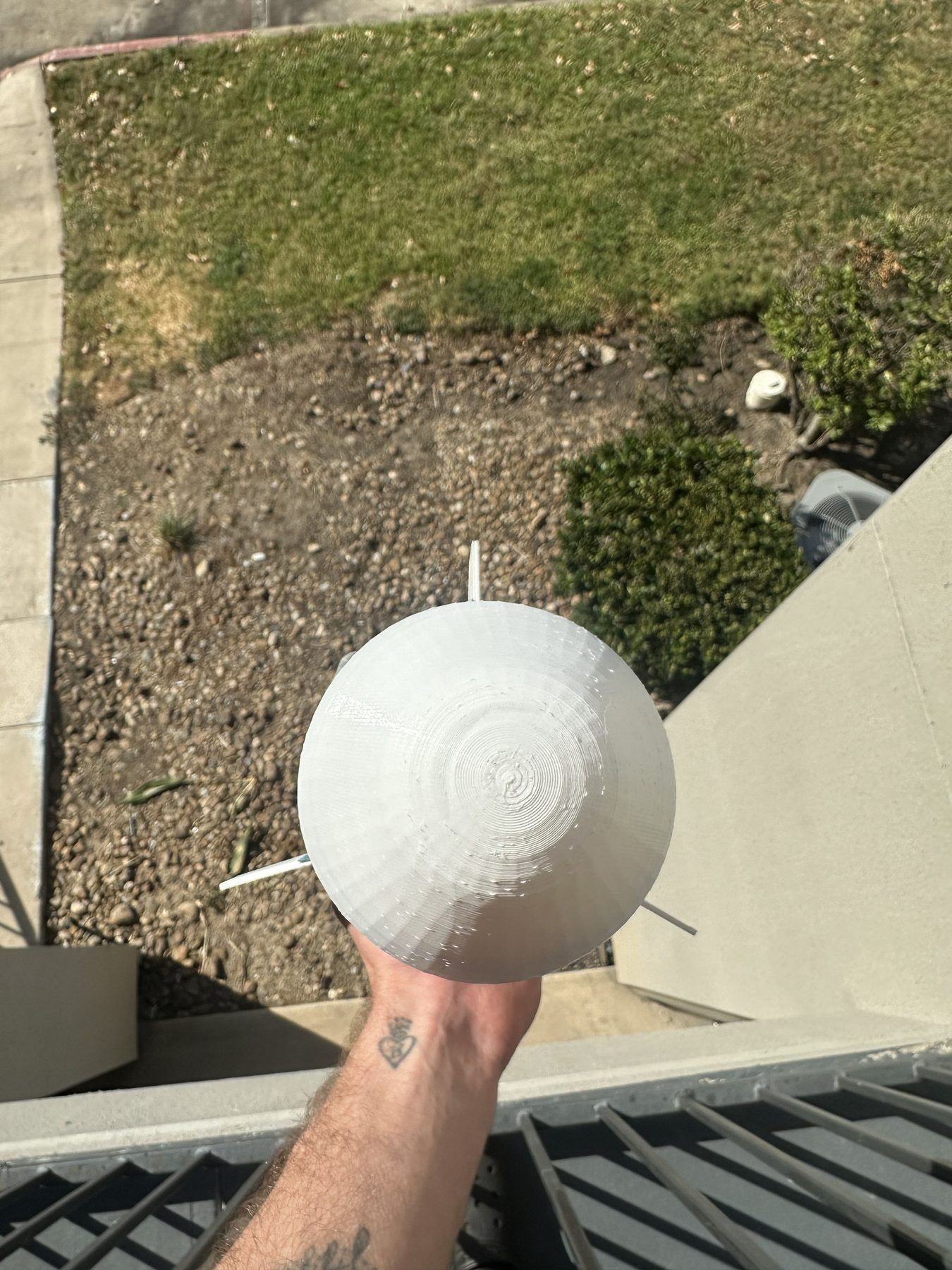
Build Media
Final build photos showing the assembled 2-liter rocket, parabolic nose cone, clipped-delta fins, and fin spacing.
Simulation and Analysis Media
MATLAB and Autodesk computational fluid dynamics (CFD) visuals arranged to match the presentation sequence: trajectory modeling first, enhanced sweep analysis second, and CFD visualization last.
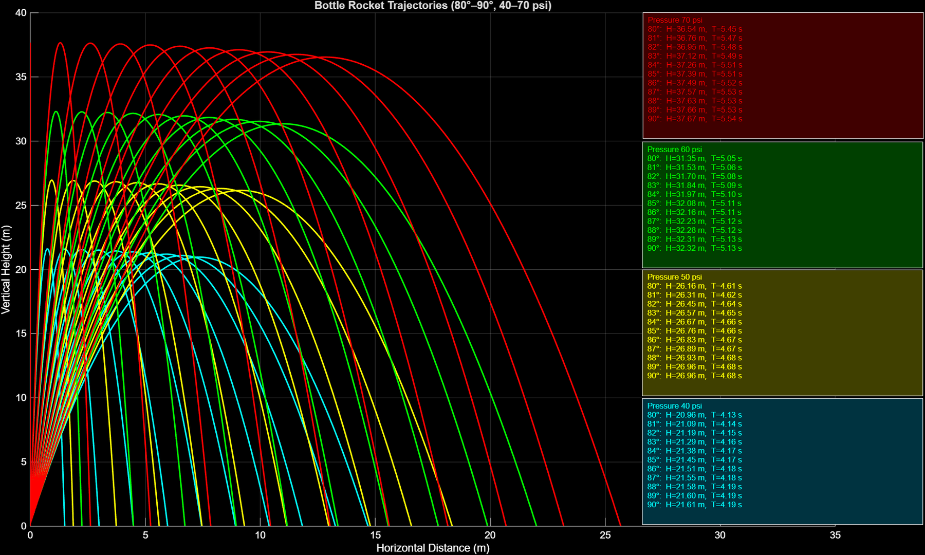
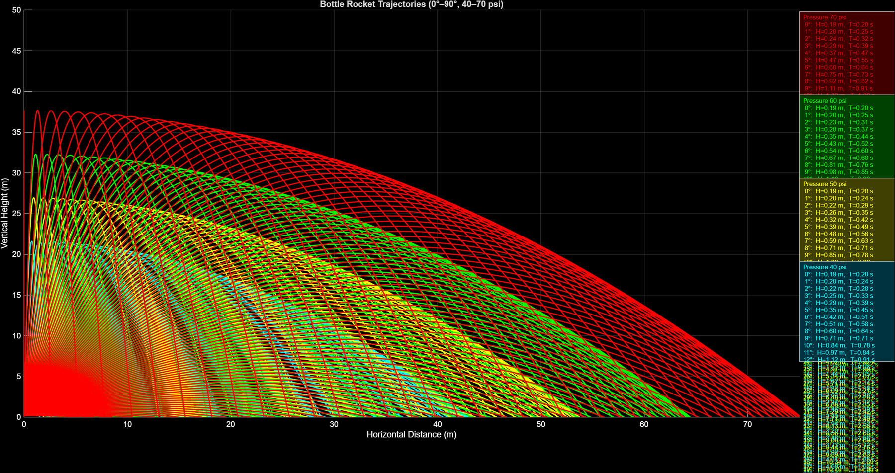
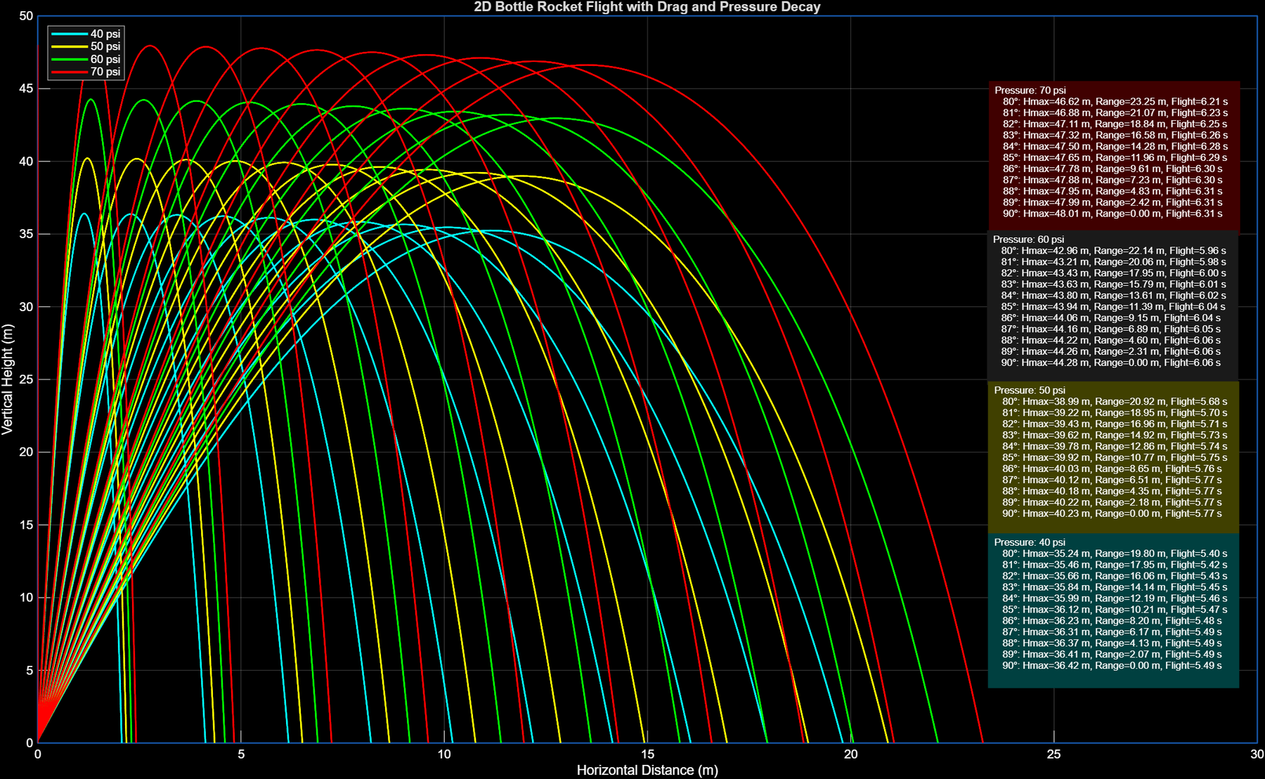
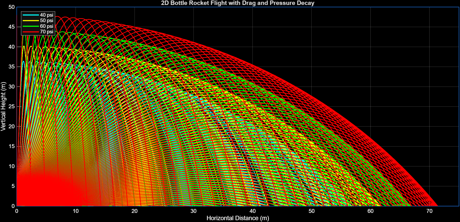
MATLAB Trajectory Simulation
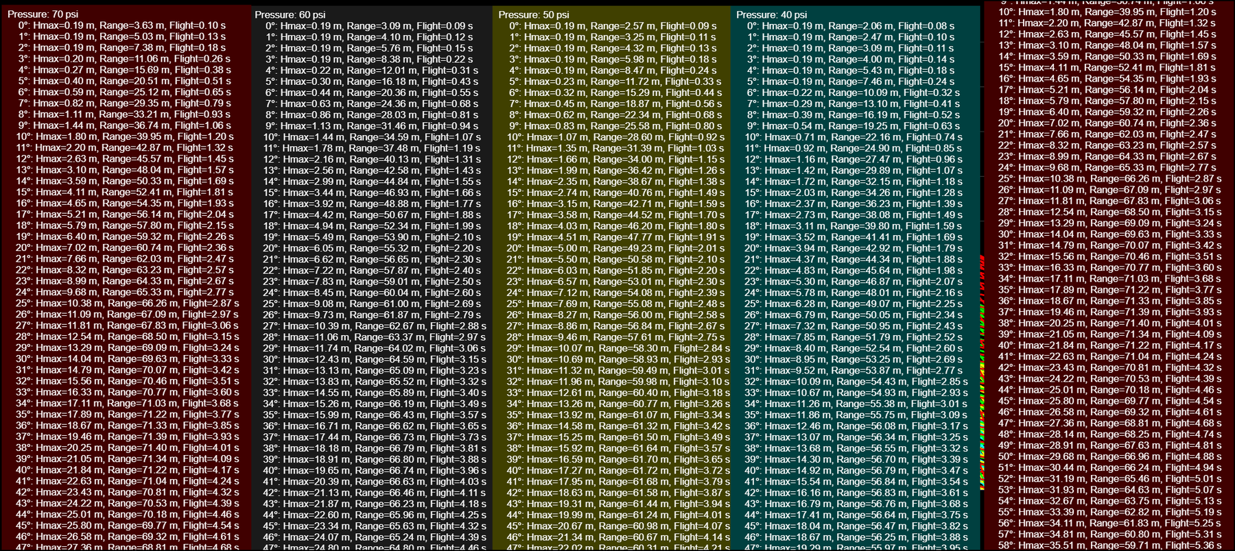
The MATLAB figures are grouped as trajectory-sweep outputs from two model types: ideal projectile motion and a more realistic model that includes drag and pressure-decay assumptions. Each model was evaluated with a smaller sweep range and a larger sweep range; the sweep range was changed by adjusting one value in the MATLAB code.
MATLAB sweep data table and critical-angle output
Autodesk CFD Visualization
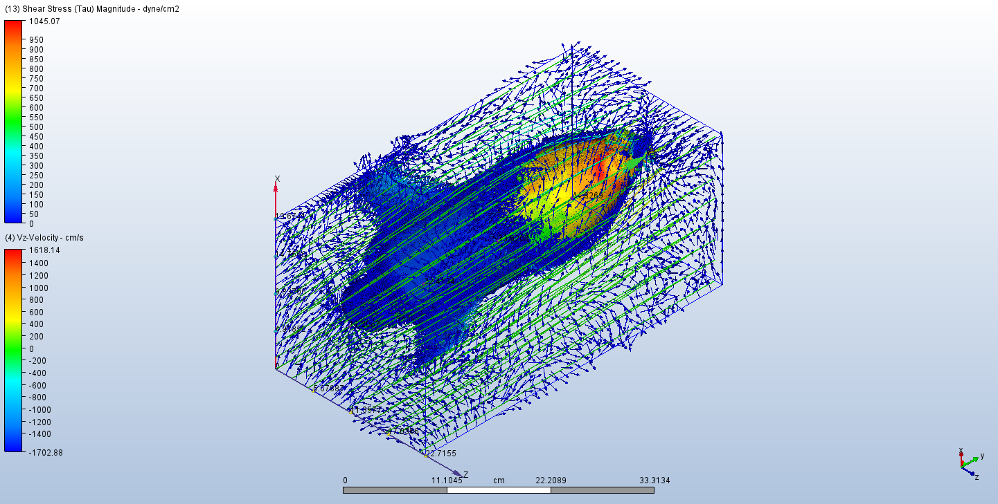
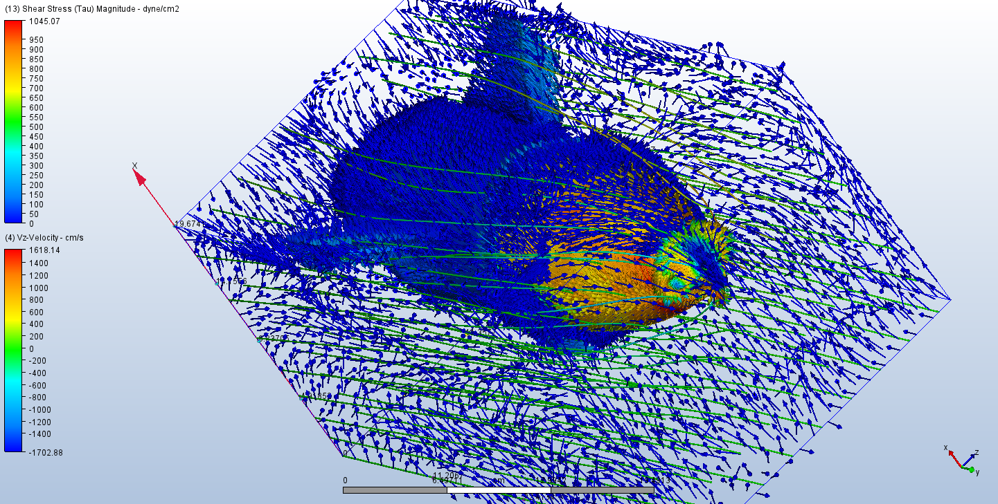
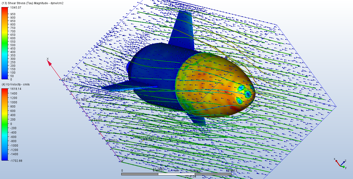
Autodesk computational fluid dynamics (CFD) was used to visualize airflow behavior around the rocket body, nose cone, and fins. The still images are now grouped by analysis purpose: shear-stress behavior, static-pressure behavior, and supplemental flow-property views.
Shear-Stress Study
These views focus on shear-stress distribution and local flow direction around the rocket body.
Static-Pressure Study
These views focus on pressure distribution around the nose, body, and fins.
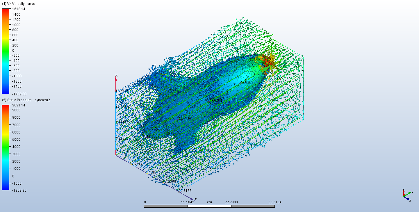
Supplemental CFD flow-property view
Key Lessons and Next Iteration
Stability First
Center-of-mass and center-of-pressure calibration should be treated as a primary design step rather than a late correction. Nose ballast improved the final experimental stability margin.
Mass and Fit Matter
Printed parts had to balance stiffness, low mass, print quality, and fit on a curved bottle body. Small fabrication details had a visible effect on alignment and repeatability.
Model-to-Test Gap
MATLAB and CFD helped guide design direction, but physical calibration and launch testing were still needed to validate real flight behavior.
Engineering Challenges
Flight Stability
Maintaining a straight flight path required balancing fin geometry, ballast, center of mass, and center of pressure.
Altimeter Mounting
The altimeter had to be mounted without creating a major imbalance or disrupting the rocket’s stability characteristics.
3D Printing Limitations
Nose cone and fin fabrication required iteration due to print quality, material behavior, and physical fit constraints.
Model-to-Test Gap
Theoretical stability predictions did not perfectly match experimental behavior, so physical calibration and testing were needed to validate the final design.
Development Workflow
Concept and Role Assignment
The team divided responsibilities across stability, fin design, nose cone design, materials research, fabrication, simulation, and final integration.
CAD and Subsystem Design
Nose cone and fin geometry were modeled and revised through multiple design iterations before final fabrication.
Simulation
MATLAB was used for projectile-motion and parameter-sweep simulations, while Autodesk CFD was used to visualize aerodynamic flow behavior.
Fabrication
The final PLA nose cone and fins were sliced, printed, and assembled onto the 2-liter bottle rocket structure.
Calibration and Launch Testing
The final rocket was calibrated using center-of-mass and center-of-pressure measurements, then flight tested to validate stability and performance.
Public Documentation Note
This portfolio page summarizes my contribution and the technical outcome of the project without posting the full original report, team meeting photos, or other materials that include classmates’ images or personal information.
The media shown here focuses on sanitized build photos, MATLAB plots, Autodesk CFD screenshots, certificate images, and project artifacts suitable for public portfolio use. Team meeting photos and personal images are excluded from the public version unless explicitly approved.
Acknowledgements
I thank Dr. Ermias Koricho and the Department of Mechanical Engineering at the University of Texas at Tyler for project guidance, resources, and use of the Ratliff Engineering Laboratory facilities.
Related Work / Contact
This project connects to my broader work in mechanical design, simulation, CAD, fabrication, instrumentation, and experimental testing.