Results import pending

HEC13 Axial Turbine CFD Performance Study

ANSYS Fluent 2026 R1 · Automated MRF Operating-Point Campaign · Interactive Post-Processing

Numerical performance characterization of an axial-flow turbine concept for a marine-energy system. The workflow combines a three-dimensional ANSYS Fluent model with automated PyFluent case execution and browser-based post-processing of torque, shaft power, pressure drop, mass flow, and power coefficient.

Model Overview

Numerical Model

  • ANSYS Fluent 2026 R1, three-dimensional pressure-based solver.
  • Steady Multiple Reference Frame (MRF) treatment of the turbine rotating region.
  • k-omega Shear Stress Transport (SST) turbulence model.
  • Water-flow operating points with automated inlet-velocity and rotor-speed sweeps.
  • Positive X-axis rotor direction selected from a two-direction screening simulation.

Reported Quantities

  • Shaft torque and mechanical shaft power.
  • Tip-speed ratio (TSR).
  • Power coefficient, CP, and torque coefficient, CQ.
  • Inlet-to-outlet pressure drop.
  • Mass-flow rate and operating-point metadata.
Successful CFD Runs Pending
Maximum Shaft Power Pending
Maximum Power Coefficient Pending
Best Tested TSR Pending

The page is already wired for the morning CFD import. Values will populate after the post-processing package is imported.

Interactive CFD Results

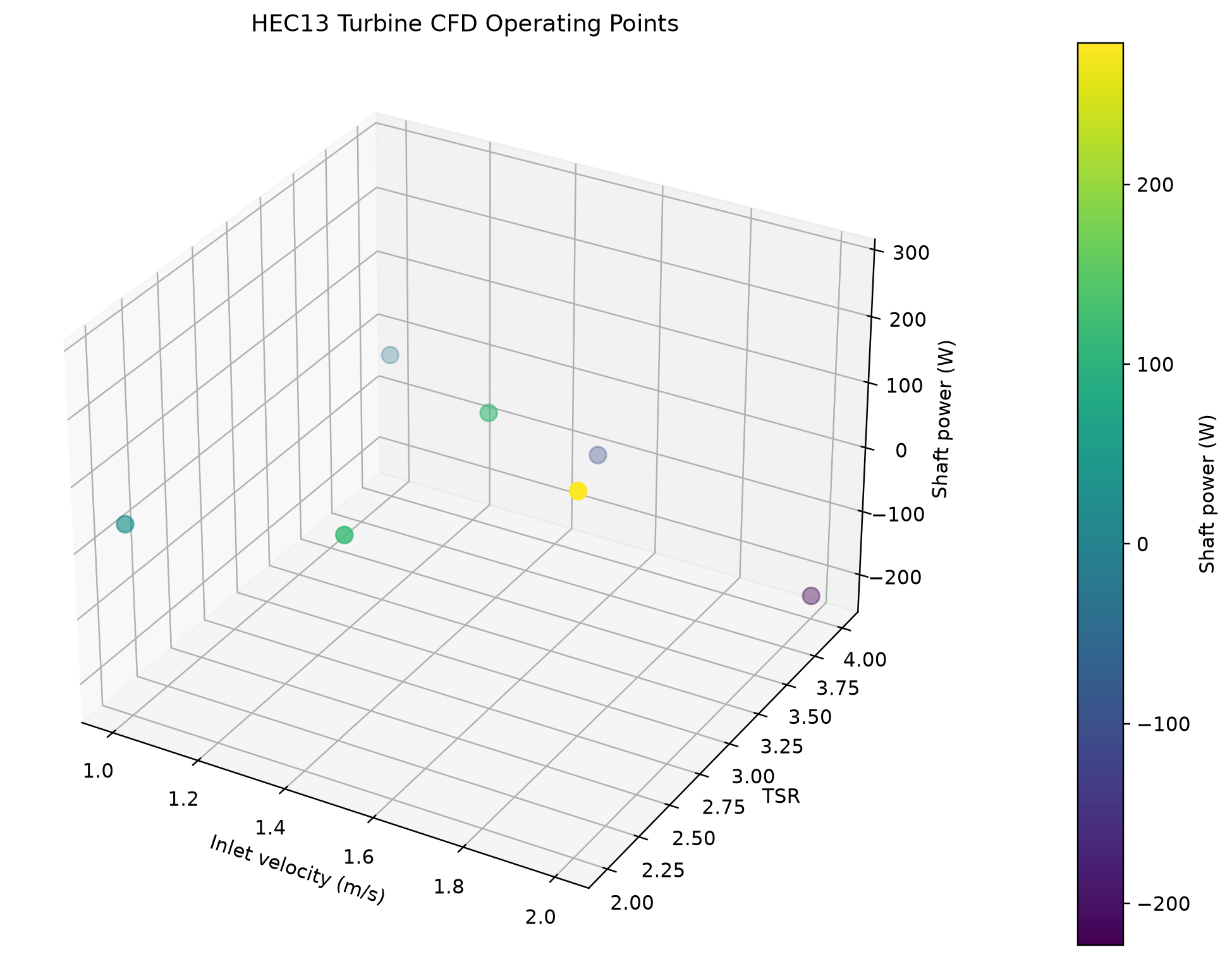
Hover over individual operating points, switch performance metrics, and rotate the three-dimensional operating map. The embedded dashboard is generated directly from the CFD campaign summary files.

Interpretation boundary: This page presents numerical CFD operating points from the current prototype geometry. The quick campaign is intended to identify promising operating regions; it is not a substitute for mesh-independence testing, transient blade-passing analysis, or experimental validation.

Presentation Figures

Static figures are populated automatically by the result-import script. Figures that have not yet been generated remain hidden.
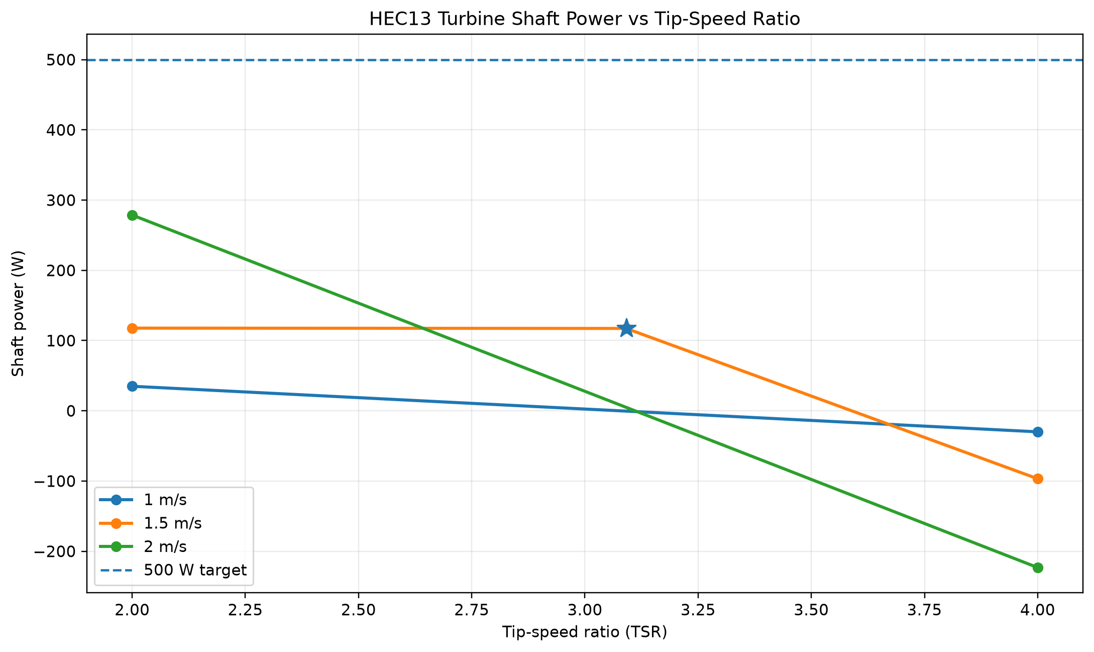
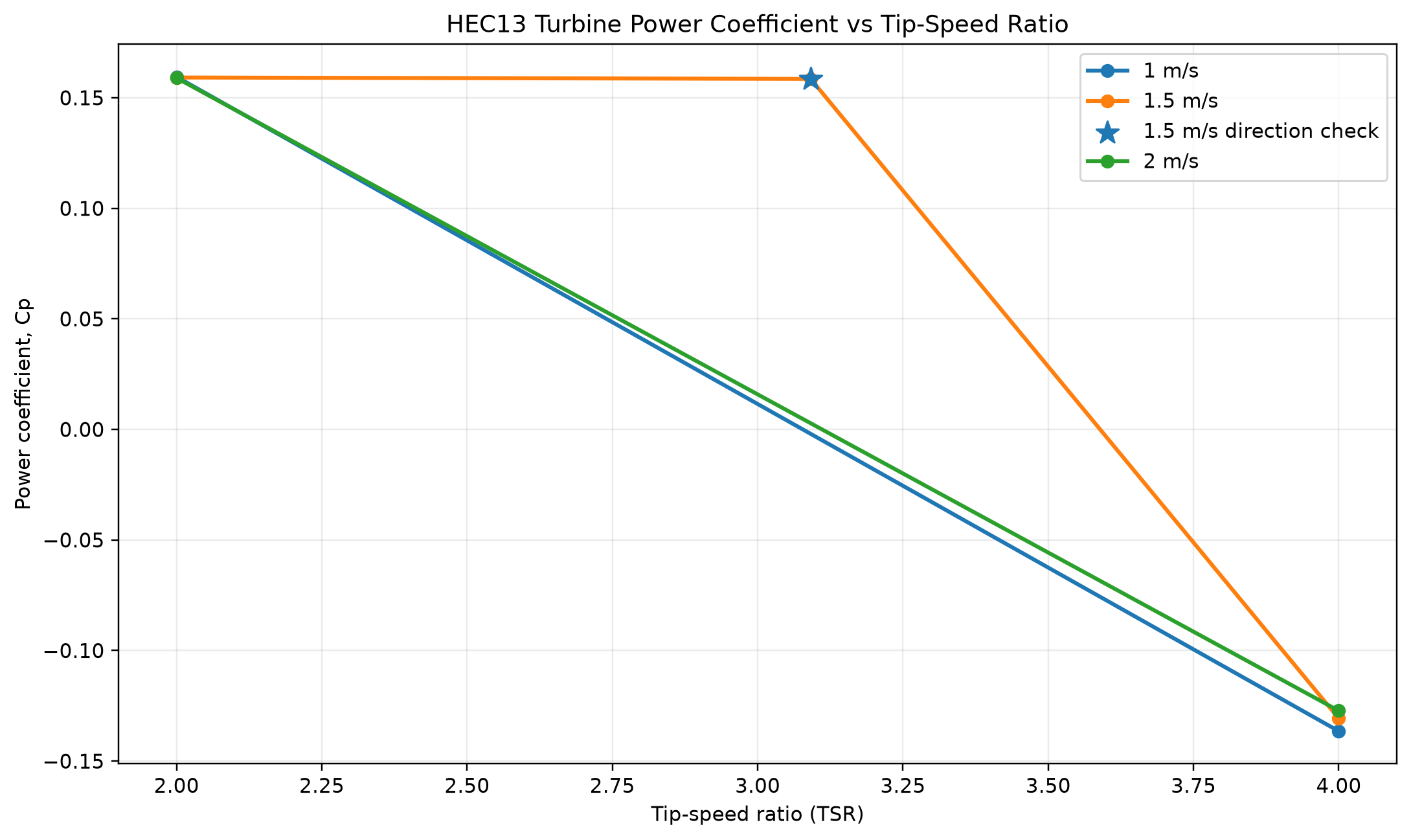
Shaft power versus tip-speed ratio
Shaft power versus tip-speed ratio.
Power coefficient versus tip-speed ratio
Power coefficient versus tip-speed ratio.
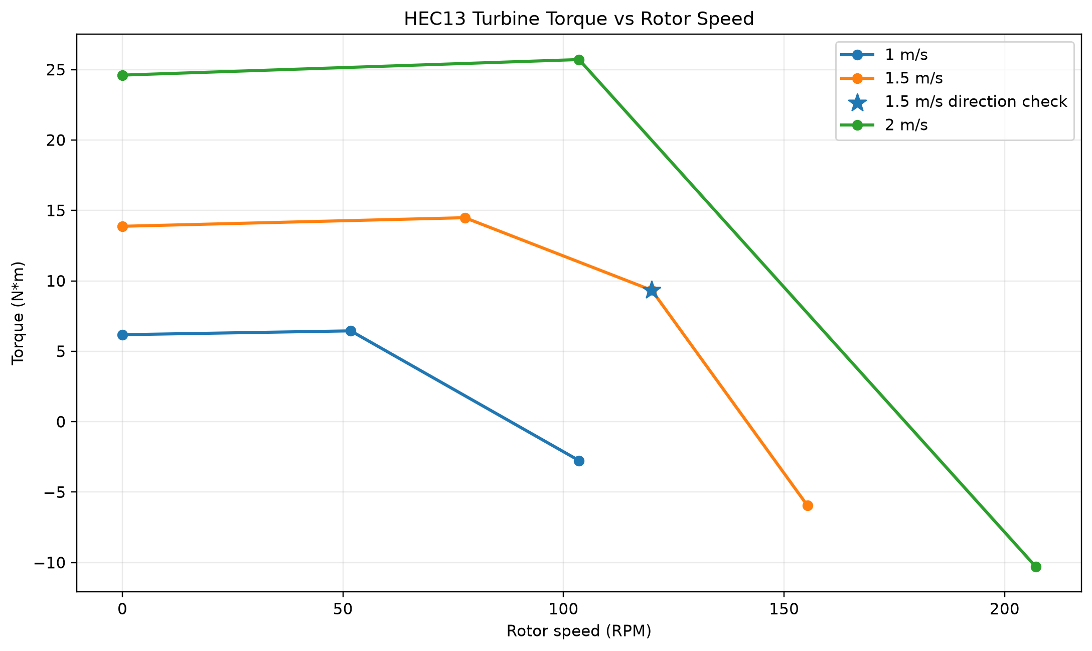
Turbine torque versus rotor speed
Hydrodynamic torque versus rotor speed.
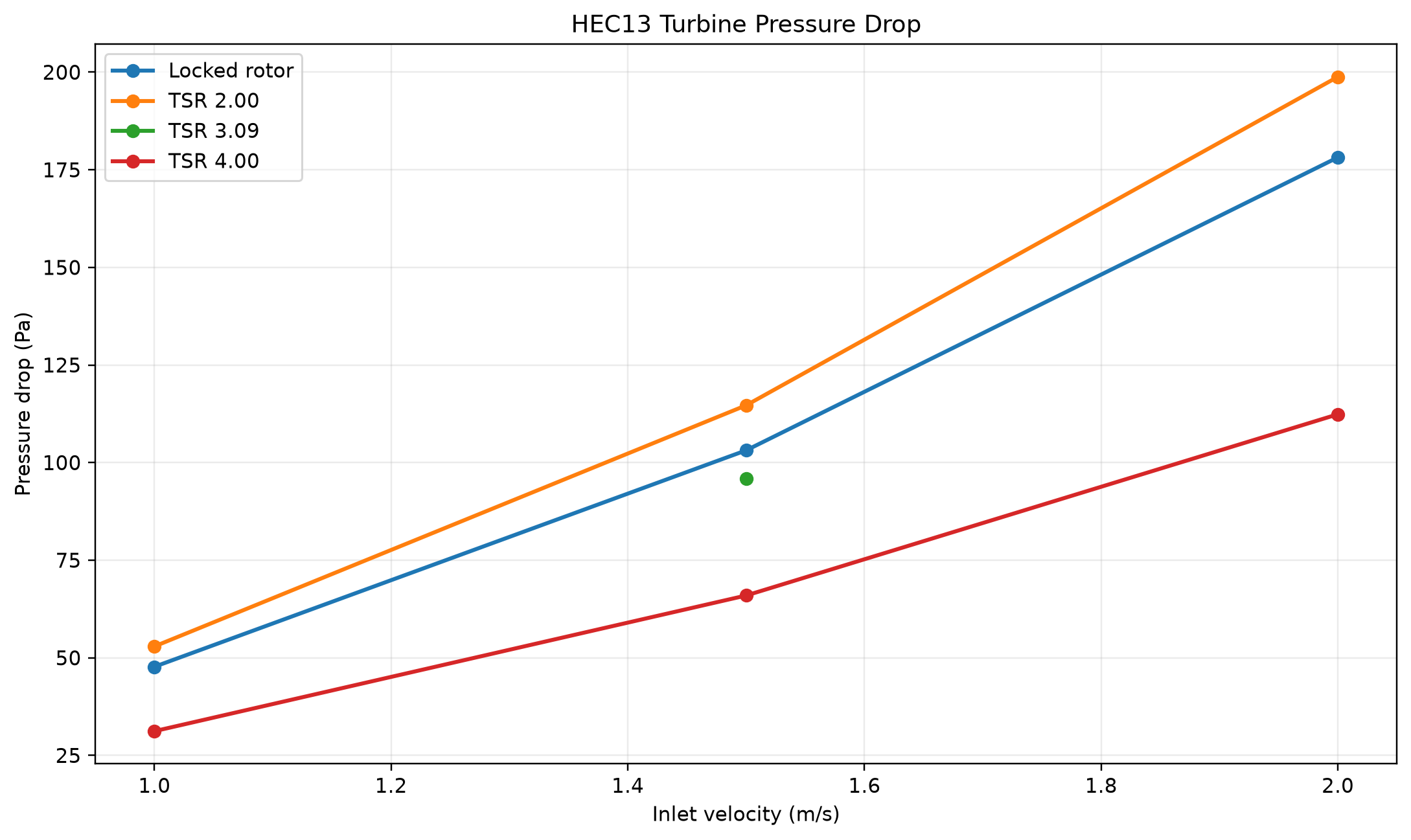
Pressure drop versus inlet velocity
Pressure drop across the modeled turbine domain.
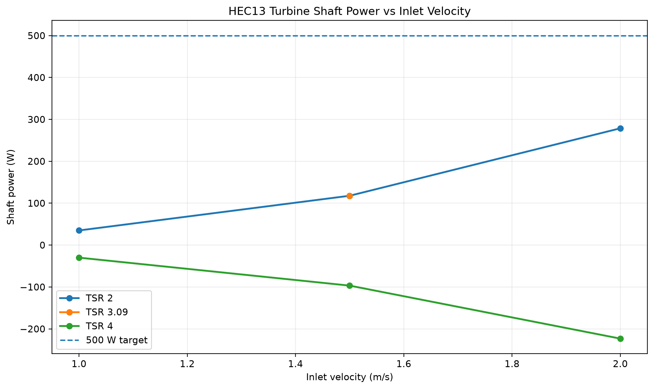
Shaft power versus inlet velocity
Shaft power scaling across tested inlet velocities.
Three-dimensional CFD operating-point scatter plot
Three-dimensional operating-point map.

Methods and Limitations

The current study uses a steady MRF approximation, which resolves operating-point behavior without resolving blade-passing transients. Reported performance values should therefore be treated as numerical model outputs for design comparison until supported by additional mesh-convergence work and physical testing.

The public dashboard intentionally exposes derived performance metrics and presentation figures rather than proprietary CAD source files or the complete Fluent case/data package.